
Multi-element alloy probe for semiconductor testing and manufacturing method of multi-element alloy probe

A multi-component alloy and manufacturing method technology, applied in the field of probe card testing, can solve problems such as complex processes, and achieve the effects of wide adaptability, low production cost, and short probe cycle.

Pending Publication Date: 2022-05-03
上海泽丰半导体科技有限公司
View PDF0 Cites 0 Cited by
  • Summary
  • Abstract
  • Description
  • Claims
  • Application Information

AI Technical Summary

Problems solved by technology

Another defect of the MEMS probe made by UV-LIGA technology is that the manufacturing process of the smaller needle tip structure is more complicated, and high-precision CMP and other processes need to be introduced

Method used


Image

  • Multi-element alloy probe for semiconductor testing and manufacturing method of multi-element alloy probe
  • Multi-element alloy probe for semiconductor testing and manufacturing method of multi-element alloy probe
  • Multi-element alloy probe for semiconductor testing and manufacturing method of multi-element alloy probe

Examples


Embodiment 2

[0087] Based on the above-mentioned embodiment, the parts that are the same as the above-mentioned embodiment in this embodiment will not be repeated one by one. This embodiment provides a method for manufacturing a multi-element alloy probe for semiconductor testing, including steps:

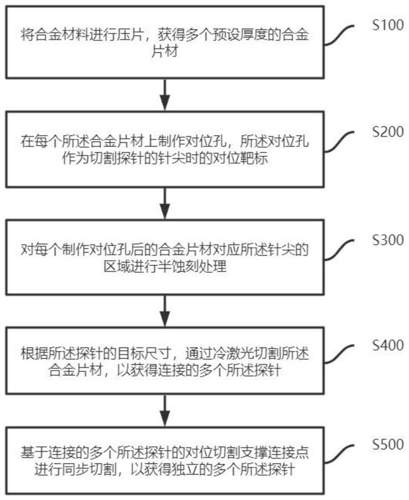
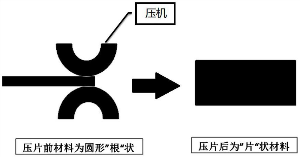
[0088] S100 presses the alloy material into sheets to obtain alloy sheets with multiple preset thicknesses. Exemplary, including steps:

[0089] S01: Use a four-axis metal tablet press to press the copper-silver alloy material with a diameter of 0.3mm. After 4-6 presses, the copper-silver metal sheet with the designed thickness is obtained. The thickness of the alloy sheet is 30-100um, which meets the size requirements of the existing wafer-level chip test probes.

[0090] Among them, the silver content in the copper-silver alloy is 1%-10%, the copper content is 90%-99%, and the tensile strength of the alloy is 400-1500Mpa. This thickness meets the existing wafer-level chip test probe size re...

Embodiment 3

[0147] A multi-element alloy probe for semiconductor testing, comprising: a multi-element alloy probe for semiconductor testing manufactured according to the manufacturing method of the multi-element alloy probe for semiconductor testing.

[0148] Specifically, such as Figure 10 As shown, it can be seen from left to right that the structure of the probe includes: a pointed head with a contact surface smaller than the needle body, an elastic body of the probe, and a needle tail with a limiting function.

[0149] The probe made by the invention has wide adaptability to probe materials, and does not need to be limited by the material limitations of electroforming alloys of traditional MEMS probes. The probe body can be obtained by traditional metallurgical methods, and rare elements can be added to form materials with special performance requirements. . The probe made by the present invention can quickly and accurately make the needle tip of the probe, and the size of the fast ...


PUM

PropertyMeasurementUnit
diameteraaaaaaaaaa

Abstract

The invention provides a multi-element alloy probe for semiconductor testing and a manufacturing method thereof, and the method comprises the steps: carrying out the tabletting of an alloy material, and obtaining an alloy sheet with a preset thickness; manufacturing an alignment hole in each alloy sheet, wherein the alignment hole is used as an alignment target when the tip of a probe is cut; carrying out half-etching treatment on an area, corresponding to the needle tip, of each alloy sheet after the alignment hole is formed; according to the target size of the probe, cutting the alloy sheet through ultrafast laser to obtain a plurality of connected probes; and performing synchronous cutting based on the alignment cutting support connection points of the plurality of connected probes so as to obtain the plurality of independent probes. The semiconductor test probe manufactured by the invention breaks through the limitation of an MEMS probe process on electroplating materials and performance, and the submicron processing precision of the semiconductor test probe can be realized.

Description

technical field [0001] The invention relates to the technical field of probe card testing, in particular to a multi-element alloy probe for semiconductor testing and a manufacturing method thereof. Background technique [0002] Wafer Probing semiconductor wafer testing is a very important link in the semiconductor manufacturing industry. It can not only check the manufacturing defects and yield rate of the fab, but also avoid subsequent packaging waste. The probe used in wafer testing is an important functional part for communication between the testing machine and the chip under test on the wafer [0003] Existing probe technologies all originated in the last century, but due to process limitations, it is very difficult to manufacture reliable probe cards that meet high density, fine pitch, small size, and good parallelism at the same time. Based on MEMS technology, micron-nano-sized structures with good consistency and high precision can be produced in batches. The applic...

Claims


Application Information

Patent Timeline
Patent Type & Authority Applications(China)
IPC IPC(8): G01R1/067G01R3/00H01L23/544
CPCG01R1/067G01R3/00H01L22/34H01L22/32
Inventor 陶克文罗雄科张振明
Owner 上海泽丰半导体科技有限公司
Learn More