Combined crude oil electric dehydrator based on multi-field synergistic effect

An electric dehydrator, combined technology, applied in the direction of electric/magnetic dehydration/demulsification, mechanical dehydration/demulsification, hydrocarbon oil treatment, etc., can solve the problem that the centrifugal swirl strength cannot be guaranteed and the equipment structure design is complicated , sensitive operating conditions and other issues, to achieve the effect of improving the oil-water separation effect, small footprint, and high compact structure

Active Publication Date: 2022-05-17
CHINA NAT OFFSHORE OIL CORP +1
View PDF13 Cites 2 Cited by
  • Summary
  • Abstract
  • Description
  • Claims
  • Application Information

AI Technical Summary

Problems solved by technology

The rotary type with external power needs to use the motor to drive the drum or impeller to rotate through the shaft to form a swirl flow. Although the rotation intensity can be adjusted by adjusting the speed, the existence of the dynamic seal makes the equipment structure design complicated and the energy consumption is relatively high.
The non-rotating type uses stationary spiral blades or "guides" the pressurized fluid to generate rotational motion through a tangential inlet. Although the structure is simple, in order to achieve the desired swirl intensity, the inlet fluid pressure must be increased as much as possible or the radius of rotation must be reduced. , often makes the processing capacity of the single structure of the swirling flow limited, so it is not possible to use multiple single structures in parallel to increase the processing capacity, and finally the problem of occupying a large space still exists
In particular, it cannot guarantee sufficient centrifugal swirl strength and is more sensitive to operating conditions, and it is powerless when oil-water emulsification is serious

Method used


Image

  • Combined crude oil electric dehydrator based on multi-field synergistic effect
  • Combined crude oil electric dehydrator based on multi-field synergistic effect
  • Combined crude oil electric dehydrator based on multi-field synergistic effect

Examples


Embodiment Construction

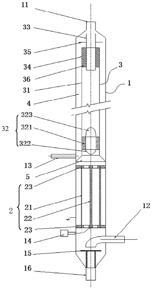
[0030] In order to make the purpose, technical solution and advantages of the present invention clearer, the technical solution of the present invention will be clearly and completely described below in conjunction with the accompanying drawings. Apparently, the described embodiments are some, but not all, embodiments of the present invention. Based on the embodiments of the present invention, all other embodiments obtained by persons of ordinary skill in the art without making creative efforts belong to the protection scope of the present invention.

[0031] In the description of the present invention, it should be noted that the orientation or positional relationship indicated by the terms "upper", "lower", "front", "rear", "inner", "outer", "horizontal", "vertical" etc. Based on the orientation or positional relationship shown in the drawings, it is only for the convenience of describing the present invention and simplifying the description, rather than indicating or implyi...


PUM


Abstract

The invention discloses a combined type crude oil electric dehydrator based on a multi-field synergistic effect. The combined type crude oil electric dehydrator comprises an outer pipe, an electrostatic coalescence section, a rotational flow section and a gravity settling section, a first oil outlet pipe is formed at the top of the outer pipe, a crude oil emulsion inlet pipe is arranged on the side close to the bottom of the outer pipe, and a first water outlet pipe is arranged on the side close to the bottom of the gravity settling section; the electrostatic coalescence section is externally connected with a positive electrode and a negative electrode, and non-uniform electric fields are formed between the electrostatic coalescence section and the outer pipe and in the electrostatic coalescence section; the rotational flow section comprises an inner pipe, a rotation starting element, a second oil outlet pipe and a second water outlet pipe, and the inner pipe is located above the electrostatic coalescence section and coaxially arranged in the outer pipe; the rotation starting element is arranged at the lower end of the inner pipe; the second oil outlet pipe is coaxially arranged at the top of the inner pipe; the second oil outlet pipe is sleeved with the second water outlet pipe, and the second water outlet pipe is arranged at the top of the inner pipe; the gravity settling section is an annular space defined by the inner pipe, the outer pipe and the transition pipe section, and the upper portion of the annular space is open.

Description

technical field [0001] The present invention relates to a high-efficiency demulsification and dehydration treatment device for offshore high-water crude oil emulsion, in particular to a combined electric dehydrator for crude oil based on multi-field synergy, especially to a device based on the comprehensive action of electric field, centrifugal force field and gravity field Crude oil dehydrator. Background technique [0002] As most of my country's onshore or offshore oil fields gradually enter the middle and late stage of exploitation, the water content in the oil well production fluid increases year by year, and some even reach as high as 95%. In order to enhance oil recovery, new technologies such as acid fracturing, water plugging and profile control, polymer flooding / chemical flooding have been proposed. Especially with the large-scale popularization and application of enhanced oil recovery (EOR) technologies such as polymer flooding and chemical flooding, the degree o...

Claims


Application Information

Patent Timeline
Patent Type & Authority Applications(China)
IPC IPC(8): C10G33/02C10G33/06C10G53/02
CPCC10G33/02C10G33/06C10G53/02C10G2300/1033
Inventor 王春升石熠陈家庆姬宜朋尚超张明王海燕郑晓鹏平朝春王艳红刘帆
Owner CHINA NAT OFFSHORE OIL CORP
Why Eureka
Try Eureka