
Buried sandwich broadband coupling calibration network

A buried, network technology, applied in the direction of radiating element structure, antenna, antenna grounding device, etc., can solve the problems of gain loss, difficult AD sampling, difficult implementation, etc., to achieve strong manufacturability, strong versatility, cost low cost effect

Pending Publication Date: 2022-05-17
10TH RES INST OF CETC
View PDF8 Cites 0 Cited by
  • Summary
  • Abstract
  • Description
  • Claims
  • Application Information

AI Technical Summary

Problems solved by technology

The phased array antenna is an array antenna composed of multiple radiating elements. Due to various reasons, such as component performance degradation or damage, strong electromagnetic interference, etc., the excitation current of each antenna element in the phased array has random Amplitude and phase errors will lead to deterioration of the side lobe level of the antenna lobe, loss of gain, and decrease in beam pointing accuracy. Therefore, corresponding means must be provided to monitor and calibrate the amplitude and phase of each antenna unit on a regular or real-time basis.
[0003] There are several traditional coupling methods for online calibration: add coupling lines or couplers to the TR component or transfer layer. This method has a complex structure, and the processing of phased array antennas with high frequencies is complex and difficult to implement.
Adding a coupling patch unit and a power combining network to the antenna array, this method needs to increase the antenna aperture area, and for a large-scale antenna array, the dynamic range is usually above 40dB, which is not easy for back-end AD sampling

Method used


Image

  • Buried sandwich broadband coupling calibration network
  • Buried sandwich broadband coupling calibration network
  • Buried sandwich broadband coupling calibration network

Examples


Embodiment Construction

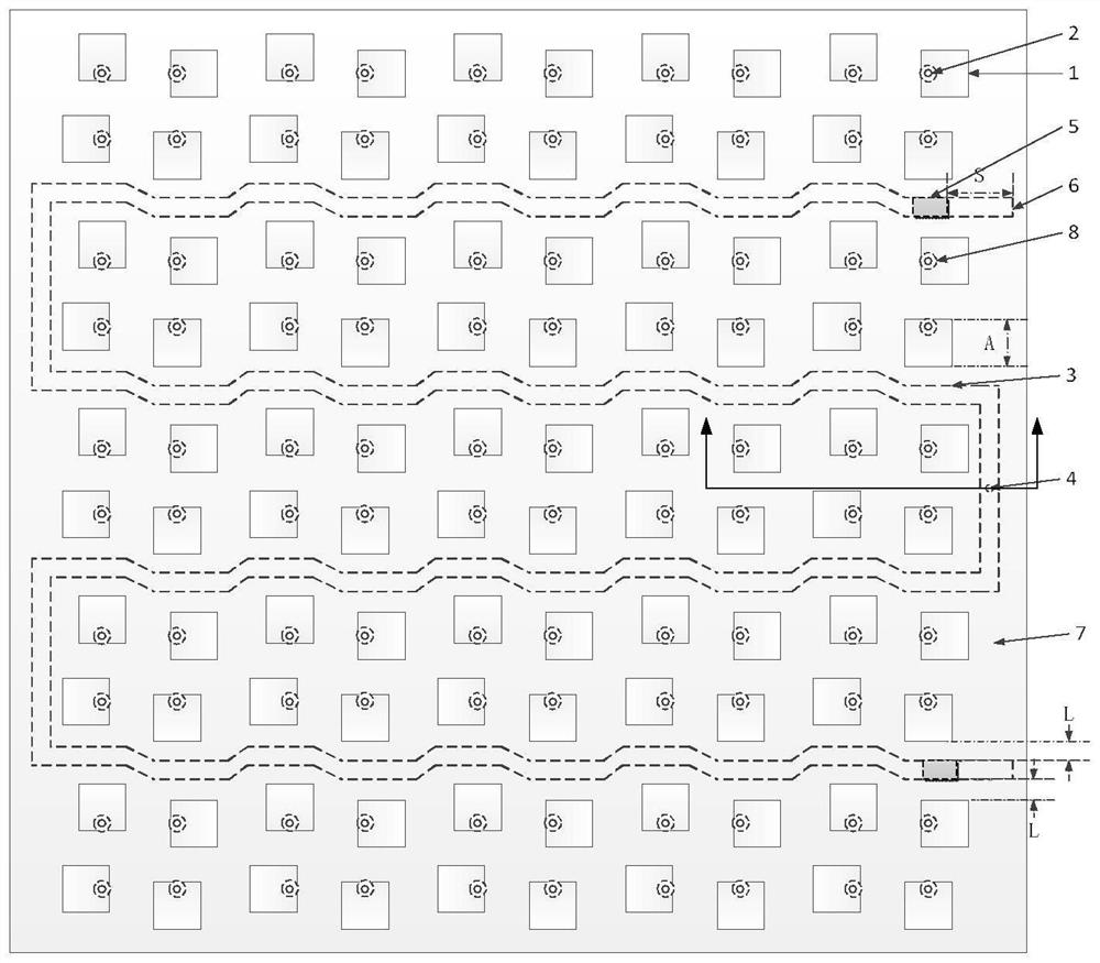
[0011] figure 1 It is the front view of the embedded sandwich broadband coupling calibration network of the present invention;

[0012] figure 2 yes figure 1 Partial cross-section of the centerline of

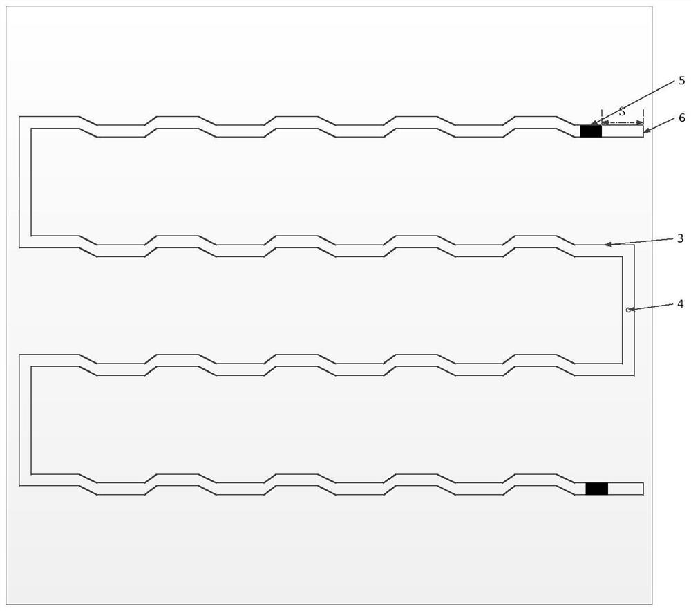
[0013] image 3 yes figure 2 Top view of the bottom dielectric board;

[0014] Figure 4 yes image 3 bottom view of

[0015] In the figure: 1 antenna patch, 2 edge feed point, 3 sandwich microstrip line network, 4 network feed point, 5 buried resistance, 6 microstrip open line, 7 metal floor, 8 floor opening.

[0016] refer to Figure 1-Figure 3 . In the exemplary preferred embodiment described below, a buried sandwich broadband coupling calibration network includes: arranged on the surface of the top layer antenna array printed board surface, the antenna patch 1 arranged in a vertical and horizontal line array dislocation array and set At the edge feed point 2 of the antenna patch 1, the metal floor 7 of the underlying medium with a floor opening 8 is formed, whe...


PUM


Abstract

The buried sandwich broadband coupling calibration network disclosed by the invention is simple in structure and easy to process, has good consistency, and does not increase the aperture area of an antenna. According to the technical scheme, a sandwich microstrip line network (3) which is continuously bent at equal intervals in an S-shaped winding traveling wave routing mode is manufactured on the upper surface of a bottom layer dielectric metal floor (7), and the sandwich microstrip line network is laminated between the metal floor and an antenna array plane printed board dielectric layer; a network feeding point (4) is arranged at the middle blind end of the S-shaped fold of the sandwich microstrip line network, buried resistors (5) and a microstrip open-circuit line (6) are connected in series with the head end and the tail end of an opening of the S-shaped winding traveling wave routing of the sandwich microstrip line network, and the sandwich microstrip line network corresponds to antenna patches (1) arrayed on the surface of the top-layer antenna array plane printed board. And separating the at least two rows of antenna patches at equal intervals for mutual energy coupling. The method can be used for coupling calibration of an antenna array, especially a millimeter wave large-scale antenna array.

Description

technical field [0001] The invention relates to the field of wireless communication, and relates to a calibration network of a phased array antenna system, specifically a buried sandwich broadband coupling calibration network. Background technique [0002] The monitoring and calibration technology of active phased array antenna is a comprehensive technology that is constantly improving with the development of active phased array antenna technology. Its main task is to ensure the performance characteristics, reliability and maintainability of the antenna during the entire life cycle, and to perform fault judgment, positioning, performance evaluation and calibration of the active phased array antenna, and complete guarantee and maintenance. From a technical point of view, it belongs to the test and measurement technology, and the technology involved covers almost all aspects of electronic technology, such as antenna microwave electromagnetic field, receiver technology, test in...

Claims


Application Information

Patent Timeline
IPC IPC(8): H01Q1/38H01Q1/48H01Q1/50H01Q21/00H01Q21/06
CPCH01Q1/38H01Q1/48H01Q1/50H01Q21/0075H01Q21/065Y02D30/70
Inventor 朱朕宾任思何小峰
Owner 10TH RES INST OF CETC
Learn More