Filter bank multi-carrier passive optical network transmission system and method for sharing laser source

A filter bank, passive optical network technology, applied in the field of optical communication, can solve problems such as consumption of components and energy, degradation of transmission performance of laser signal optical signal-to-noise ratio system, and OFDM orthogonality destruction, etc., to achieve enhanced flexibility, Avoid frequency flutter and reduce the effect of out-of-band leakage

Active Publication Date: 2022-05-17
SUN YAT SEN UNIV
View PDF5 Cites 0 Cited by
  • Summary
  • Abstract
  • Description
  • Claims
  • Application Information

AI Technical Summary

Problems solved by technology

In this way, although the different frequency bands of OFDM are guaranteed to be integer multiples of the subcarrier spacing, there are different transmission distances between different users. When the relative delay exceeds the CP length, the orthogonality of OFDM will still be destroyed. Therefore, this technology is implemented in Requires extra time to work synchronously, and consumes more devices and energy for this
In addition, due to the need for the laser signal to go from the OLT to the ONU through a long-distance optical fiber, usually tens of kilometers of backhaul and the use of RSOA amplification in the ONU, the decrease in the optical signal-to-noise ratio of the laser signal during transmission and amplification will lead to a decrease in system transmission performance.

Method used


Image

  • Filter bank multi-carrier passive optical network transmission system and method for sharing laser source
  • Filter bank multi-carrier passive optical network transmission system and method for sharing laser source
  • Filter bank multi-carrier passive optical network transmission system and method for sharing laser source

Examples


Embodiment 1

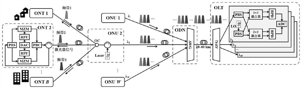
[0074] like figure 1 As shown, a filter bank multi-carrier passive optical network transmission system for sharing a laser source includes an optical network terminal ONT, an optical network unit ONU, an optical distribution network unit ODN, and an optical line terminal OLT;

[0075] In a community, an optical network terminal (Optica Line Terminal, ONT) is installed at the junction of public places and users and buildings. The user's data is transmitted through the existing copper network and arrives at the ONT; at the ONT of the optical network terminal, after digital signal processing DSP, the digital signal is converted into an analog electrical signal through a digital-to-analog converter (DAC), which is used in the optical network. Frequency division multiplexing is implemented between network terminal ONTs. The electrical signals of different optical network terminal ONTs undergo radio frequency up-conversion of different frequencies. After up-conversion, the electrica...

Embodiment 2

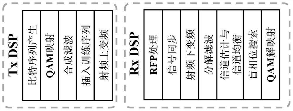
[0081] like figure 2 As shown, this embodiment provides a multi-carrier passive optical network transmission method for a filter bank sharing a laser source, using the filter bank multi-carrier passive optical network transmission system for sharing a laser source described in Embodiment 1, when sending The digital signal processing DSP flow of the terminal includes:

[0082] S11. Generate a bit sequence to be transmitted;

[0083] S12. Map the bit sequence into quadrature amplitude modulation QAM constellation points;

[0084] S13. Perform synthesis filtering to generate a filter bank multi-carrier FBMC signal;

[0085] S14. add a training sequence for synchronization and channel estimation; the training sequence is a number of known filter bank multi-carrier FBMC symbols;

[0086] S15. Up-convert the signal radio frequency; for the signals of different optical network terminal ONTs, in order to perform frequency division multiplexing, the radio frequency up-conversion ne...

Embodiment 3

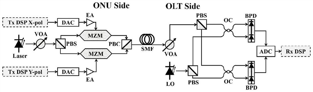
[0130] In order to illustrate the scheme created by the present invention, the experimental configuration adopted is as follows: image 3 shown. For the convenience of experimental verification, a system of two ONTs is used to simulate the uplink situation of frequency division multiplexing, and the FBMC signal is compared with the OFDM signal to verify the Multiple Access Interference (Multiple Access Interference) caused by out-of-band leakage. MAI) situation. Among them, the MAI level is characterized by the Error Vector Magnitude (EVM) of the constellation diagram. In addition, since multiple ONTs share the cost of the laser, the proposed system can use a lower linewidth laser under the same device cost. The significance of the linewidth to the system performance is also verified below.

[0131] In the experimental verification, four prototype filters of FBMC are used, including PHYDYAS (Physical Layer For Dynamic Spectrum Access and Cognitive Radio), Extended Gaussian F...


PUM


Abstract

The invention relates to a filter bank multi-carrier passive optical network transmission system and method of a shared laser source. Through a mode of sharing a light source for different frequency bands, interference of laser fluttering on frequency band intervals is avoided. When the asynchronous frequency bands using the same light source flutter at the frequency of the laser, the asynchronous frequency bands have common frequency spectrum position fluttering, so that the frequency fluttering of the laser cannot cause frequency band aliasing and crosstalk, and a protection interval does not need to be reserved for the fluttering of the laser. Compared with an OFDM signal, the FBMC signal is used, so that out-of-band leakage is greatly reduced, the required frequency spectrum protection interval is further reduced, and the frequency spectrum efficiency is greatly enhanced; the high bandwidth of the single wavelength is allocated through frequency division multiplexing, a GHz-level frequency band is provided for a user to use high-order modulation, the problem of minimum interval of wavelength division multiplexing does not exist, and the spectrum allocation flexibility is greatly enhanced; according to the invention, no long-distance back transmission of laser signals is realized, and only short-distance back transmission is realized, so that the need of laser signal amplification and reduction of the optical signal-to-noise ratio of more laser signals are avoided.

Description

technical field [0001] The present invention relates to the technical field of optical communication, and more particularly, to a filter bank multi-carrier passive optical network transmission system and method for sharing a laser source. Background technique [0002] Wavelength division multiplexed filter bank multi-carrier (Filterbank Multicarrier, FBMC) passive optical network (Passive Optical Network, PON) uplink architecture: The architecture is as follows figure 1 shown. The architecture is to allocate different frequency bands of the available bandwidth to the Optical Network Unit (ONU). The wavelength division multiplexed FBMC-PON allocates a laser source to each user, and the laser source passes through a Polarization Controller (PC). Input to Mach-Zehnder modulator (MZM). Each laser source works at different wavelengths at a certain wavelength interval (denoted as λ 1 ~λ W ), the wavelength separation is large enough to avoid spectral aliasing of different user...

Claims


Application Information

Patent Timeline
Patent Type & Authority Applications(China)
IPC IPC(8): H04J14/02H04Q11/00H04B10/50H04B10/556H04B10/69
CPCH04J14/0227H04Q11/0062H04B10/503H04B10/5563H04B10/697Y02D30/70
Inventor 李凡王晓武
Owner SUN YAT SEN UNIV
Why Eureka
Try Eureka