Constant-current-to-constant-voltage conversion topology system and control method thereof

A constant current to constant voltage, topology technology, applied in the direction of DC power input conversion to DC power output, AC power input conversion to DC power output, control/regulation system, etc., can solve the problem of wide frequency adjustment range, limited application, and large loss and other issues to achieve high efficiency and broaden the scope of application

Pending Publication Date: 2022-05-20
CHINA UNIV OF GEOSCIENCES (WUHAN)
View PDF0 Cites 2 Cited by
  • Summary
  • Abstract
  • Description
  • Claims
  • Application Information

AI Technical Summary

Problems solved by technology

[0004] (1) The conversion from constant current to constant voltage can be carried out through the push-pull transformer, which can realize the conversion from constant current to constant voltage, and the output voltage ripple is small, but the actual conversion rate is low, the loss is large, and high efficiency cannot be achieved
[0005] (2) The constant current to constant voltage conversion is performed through a resonant constant current to constant voltage converter. However, the gain characteristics of the resonant converter are not sensitive to the change of switching frequency, and a wide frequency adjustment range is required, which limits its use in underwater constant current to constant voltage conversion. Applications in pressure transformation

Method used


Image

  • Constant-current-to-constant-voltage conversion topology system and control method thereof
  • Constant-current-to-constant-voltage conversion topology system and control method thereof
  • Constant-current-to-constant-voltage conversion topology system and control method thereof

Examples


Embodiment Construction

[0045] In order to have a clearer understanding of the technical features, purposes and effects of the present invention, the specific implementation manners of the present invention will now be described in detail with reference to the accompanying drawings.

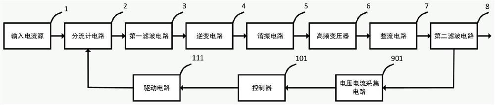
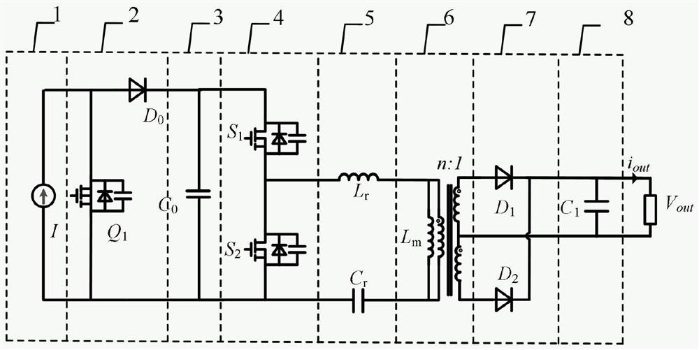
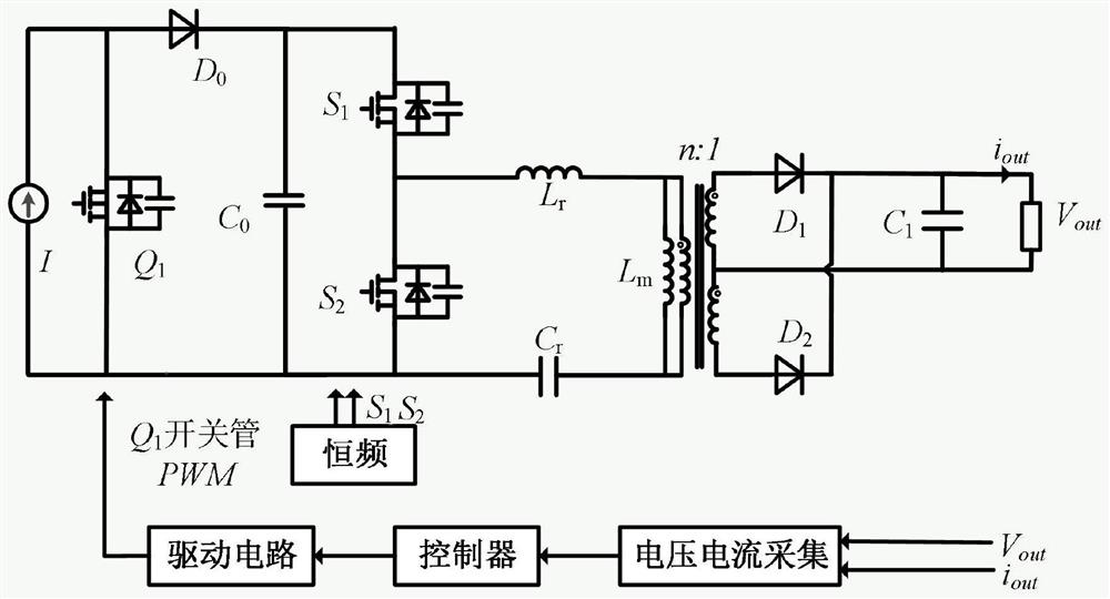
[0046] Embodiments of the present invention provide a constant current to constant voltage conversion topology system and its control method, which can convert a constant current source into an adjustable constant voltage source, Figure 1-Figure 6 They are respectively a schematic diagram of a constant-current-to-constant-voltage conversion topology system and a circuit diagram of an embodiment of the present invention.

[0047] Such as figure 1 as shown, figure 1 It is a constant current to constant voltage conversion topology system, which includes an input current source 1, a shunt circuit 2, a first filter circuit 3, an inverter circuit 4, a resonant circuit 5, a high frequency transformer 6, a rectifier circuit 7...


PUM


Abstract

The invention provides a constant-current-to-constant-voltage conversion topology system and a control method thereof. The constant-current-to-constant-voltage conversion topology system comprises a shunt meter circuit, a first filter circuit, an inverter circuit, a resonance circuit, a high-frequency transformer, a rectifying circuit, a second filter circuit, a voltage and current acquisition circuit, a controller circuit and a driving circuit. The shunt meter circuit is connected with an input current source to realize conversion from a current source to a voltage source, and meanwhile, a higher voltage is generated at the front end. The first filter circuit is connected with the output of the shunt meter, and the LLC resonant circuit is connected with the first filter circuit, is firstly inverted into high-frequency alternating current through the inverter circuit, and then supplies power to a load after being isolated by the resonant circuit and the transformer and rectified and filtered by the rectifying circuit. According to the invention, constant-current to constant-voltage conversion can be realized, and wide input and load changes can be endured. And meanwhile, a switching tube of the post-stage LLC resonant converter can realize ZVS (Zero Voltage Suppressor) opening, and a secondary rectifier diode is also a ZVS switch, so that relatively high efficiency can be achieved.

Description

technical field [0001] The invention relates to the technical field of power electronics and power automation equipment, in particular to a constant-current-to-constant-voltage conversion topology system and a control method thereof. Background technique [0002] Understanding the ocean is a prerequisite for developing ocean strategy and building a maritime power. It is necessary to establish a seabed observation network to explore ocean resources and ensure ocean security. The power supply system is an important guarantee for the normal operation of equipment such as submarine communication and observation networks. It is necessary to conduct in-depth research on underwater high-reliability power supply technology to realize safe and reliable operation of underwater electrical equipment. For the current submarine power supply mode, DC constant current power supply has high transmission efficiency and good resistance to seawater short-circuit faults. It is very suitable for...

Claims


Application Information

Patent Timeline
Patent Type & Authority Applications(China)
IPC IPC(8): H02M3/335H02M1/36H02M1/14H02M7/537H02M7/217
CPCH02M3/33507H02M1/36H02M1/14H02M7/537H02M7/217Y02B70/10
Inventor 夏远庚方支剑谢非岳浩江蔡杰
Owner CHINA UNIV OF GEOSCIENCES (WUHAN)
Why Eureka
Try Eureka