Shielding permanent magnet synchronous motor direct connection waterwheel type oxygenation system

A permanent magnet synchronous motor, waterwheel type technology, applied in the direction of magnetic circuit shape/style/structure, electric components, electromechanical devices, etc., can solve the problems of poor cooling effect of the motor, good oxygen increasing effect, DC motor damage, etc. Achieve the effect of prolonging the cycle of maintenance and adding water, improving heat dissipation efficiency and heat dissipation effect, and improving service life

Active Publication Date: 2022-05-31
浙江浙水工贸有限公司
View PDF19 Cites 0 Cited by
  • Summary
  • Abstract
  • Description
  • Claims
  • Application Information

AI Technical Summary

Problems solved by technology

[0003] For example, the Chinese patent application number (CN201810890148.5) discloses a waterwheel type aerator, including a driving mechanism, a bracket, an impeller and a pontoon. The driving mechanism includes a DC motor, a motor casing and a control box. The structure of the application Relatively balanced, the effect of oxygenation is good, and the waterproof performance is also good, but the heat dissipation effect of the motor is not good. The DC motor is waterproofed through the motor cover, the ventilation effect is poor, and the heat cannot be dissipated. It is still easy to cause damage to the DC motor due to overheating when used or used in hot seasons, so it is necessary to improve the heat dissipation of the motor.

Method used


Image

  • Shielding permanent magnet synchronous motor direct connection waterwheel type oxygenation system
  • Shielding permanent magnet synchronous motor direct connection waterwheel type oxygenation system
  • Shielding permanent magnet synchronous motor direct connection waterwheel type oxygenation system

Examples


Embodiment 1

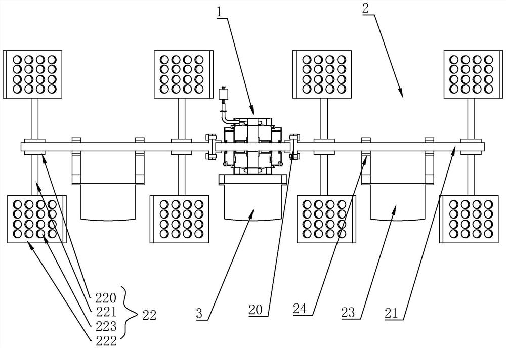
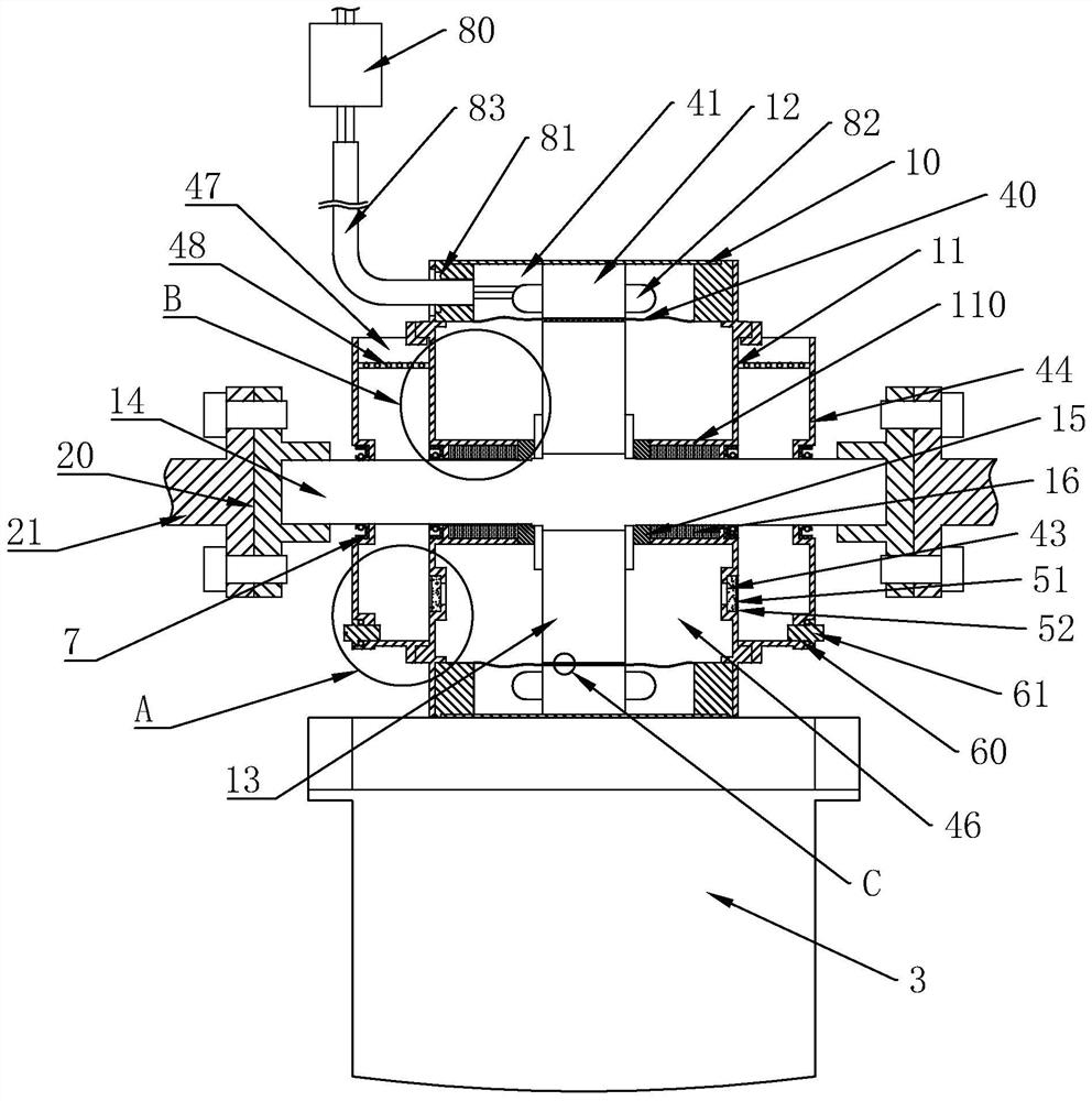
[0068] This embodiment provides a shielded permanent magnet synchronous motor 1 directly connected to the waterwheel type oxygenation system, including a motor 1, a waterwheel assembly 2 and a main pontoon 3, the motor 1 includes a casing 10, and is installed on both sides of the casing 10 The connection plate 11 at the end, the stator 12 fixed on the inner wall of the casing 10, and the rotor 13 coaxial with the stator 12 and movably connected, the rotor 13 is provided with a rotor shaft 14, and both ends of the rotor shaft 14 are connected through The disc 11 extends to the outside of the connecting disc 11, and the water wheel assembly 2 is installed at both ends of the rotor shaft 14, and also includes:

[0069] A shielding sleeve 40, the shielding sleeve 40 is installed between the two connection plates 11, and is connected with the side of the casing 10 close to the axis, and forms a shielding cavity 41 with the casing 10, the stator 12 is located in the shielding In the...

Embodiment 2

[0077] In this embodiment, in addition to including the structural features of Embodiment 1, it further includes:

[0078] A water inlet 47, the water inlet 47 is set on the top of the water storage tank 44;

[0079] A shielding frame 48, which is installed on the inner wall of the water storage tank 44 close to the water inlet 47;

[0080] Wherein, the shielding frame 48 is formed by crossing a plurality of round rods; the water storage tank 44 and the shielding frame 48 are preferably made of plastic material, and the plurality of round rods are preferably integrally formed, and preferably between the water storage tank 44 Bonding is used.

[0081] In this embodiment, it can be seen that by opening a water inlet 47 at the top of the water storage tank 44, and setting a shield frame 48 at the water inlet 47, through the operation of the water wheel assembly 2, part of the splashed water enters the water storage tank from the water inlet 47. 44, it can prolong the cycle of m...

Embodiment 3

[0083] In this embodiment, in addition to including the structural features of Embodiment 2, it further includes:

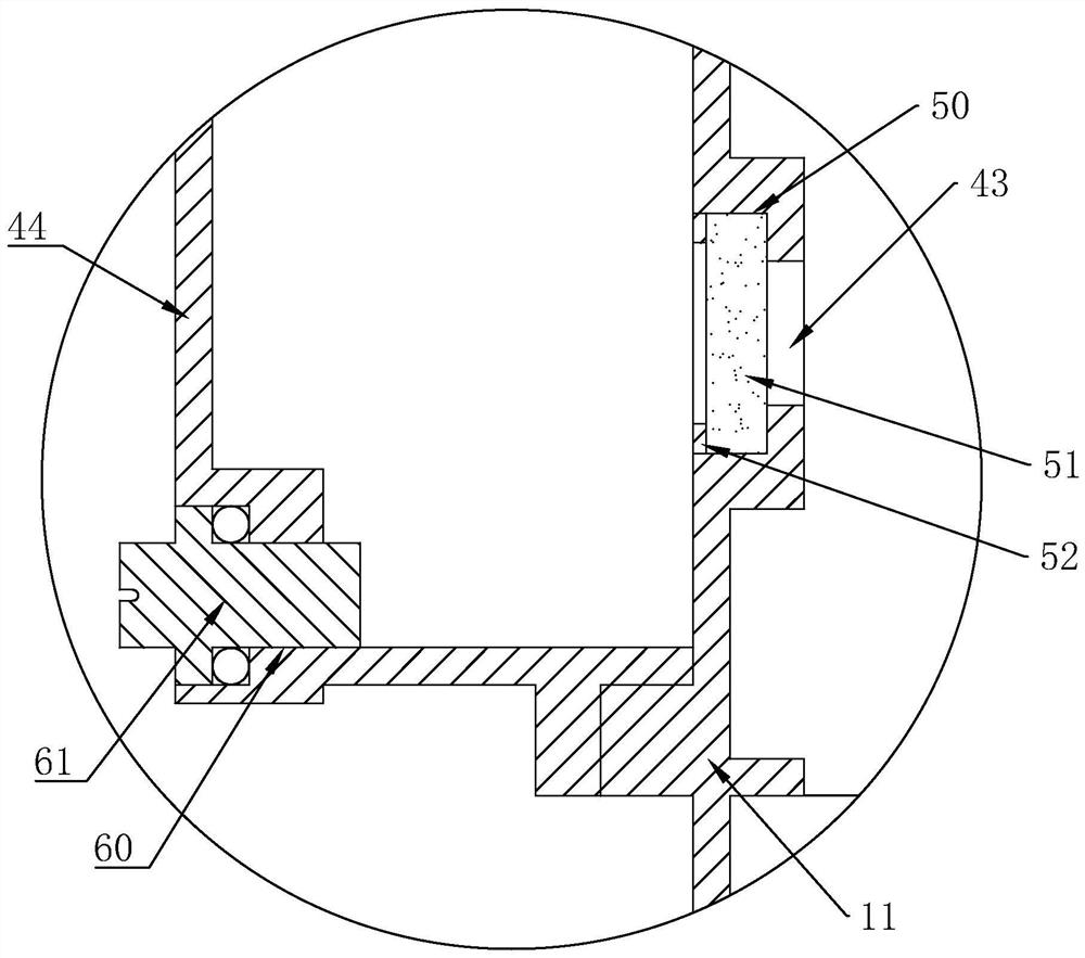
[0084] The installation groove 50, the installation groove 50 is opened on the side of the connection plate 11 close to the water storage tank 44, and is coaxially arranged with the water hole 43;

[0085] Filter cotton 51, the filter cotton 51 is installed in the installation groove 50;

[0086] A retaining ring 52, the retaining ring 52 is detachably connected to the inner wall of the installation groove 50, and is used to install the filter cotton 51 in the installation groove 50;

[0087] Wherein, the retaining ring 52 and the inner wall of the installation groove 50 are preferably clamped, and interference fit or threaded connection may also be used.

[0088] It can be seen from this embodiment that by setting the filter cotton 51 at the water hole 43, the water entering the water storage chamber 46 and the water gap 45 can be filtered, thereby preventing i...


PUM


Abstract

The invention discloses a shield permanent magnet synchronous motor direct connection waterwheel type oxygenation system, and aims to provide the shield permanent magnet synchronous motor direct connection waterwheel type oxygenation system which adopts water cooling type heat dissipation and is good in heat dissipation effect. Comprising a motor, waterwheel assemblies and a main pontoon, the motor comprises a machine shell, connecting discs, a stator and a rotor, a rotor shaft is arranged in the rotor in a penetrating mode, the two ends of the rotor shaft penetrate through the connecting discs and extend out of the connecting discs, the waterwheel assemblies are installed at the two ends of the rotor shaft, and the shielding sleeve is installed between the two connecting discs and connected with one side of the machine shell; the water passing hole is formed in the surface close to the bottom end of the connecting disc; the water storage tank is arranged on the surface of the motor and is communicated with the water passing hole; wherein a water passing gap is formed between the shielding sleeve and the rotor, a water storage cavity is formed among the shielding sleeve, the connecting disc and the rotor, and the water passing hole is communicated with the water storage cavity and the water storage tank.

Description

technical field [0001] The invention belongs to the technical field of aquaculture, in particular to a shielded permanent magnet synchronous motor directly connected to a waterwheel type aeration system. Background technique [0002] The water wheel aerator is a kind of equipment widely used in aquaculture industry. Its main function is to increase the oxygen content in the water to ensure that the fish in the water will not be hypoxic, and it can also inhibit the growth of anaerobic bacteria in the water. , to prevent the pool water from deteriorating and threatening the aquatic production environment. In many high-yield areas of aquaculture, the aerator plays the role and contributes the most to the output. [0003] For example, the Chinese patent application number (CN201810890148.5) discloses a waterwheel type aerator, including a driving mechanism, a bracket, an impeller and a pontoon. The driving mechanism includes a DC motor, a motor casing and a control box. The stru...

Claims


Application Information

Patent Timeline
Patent Type & Authority Applications(China)
IPC IPC(8): H02K1/32H02K1/20H02K5/10H02K5/20H02K5/18H02K5/14H02K9/22H02K9/193A01K63/04
CPCH02K1/32Y02W10/10
Inventor 张文敏
Owner 浙江浙水工贸有限公司
Why Eureka
Try Eureka