Waste heat recovery system matched with HISMELT smelting reduction ironmaking system

A waste heat recovery system and system technology, applied in waste heat treatment, lighting and heating equipment, furnaces, etc., can solve the problems of reduced heat transfer effect of waste heat boilers, serious safety hazards, slagging of heat exchange tubes, etc., to save purification treatment costs , prolong the service life and improve the effect of heat exchange

Pending Publication Date: 2022-06-17
SUZHOU HAILU HEAVY IND +1
View PDF15 Cites 1 Cited by
  • Summary
  • Abstract
  • Description
  • Claims
  • Application Information

AI Technical Summary

Problems solved by technology

[0005] The above-mentioned waste heat recovery system in the HISMELT smelting reduction ironmaking system has the following technical problems during operation: the high-temperature flue gas after the high-temperature cyclone separator removes large particles still contains a lot of high-temperature cohesive dust with small particle diameters The characteristic of this high-temperature cohesive dust particle is that its surface temperature is relatively low, but its internal core temperature is still high, that is, the small-sized cohesive dust remaining in the high-temperature gas has not been completely cooled. It is very easy for the dust to stick to the tube wall of the heat exchange tube in the waste heat boiler, thus forming slagging on the tube wall of the heat exchange tube, and it will accumulate more and more, which will easily cause large pieces to fall off and block
As time goes by, the heat transfer effect of the waste heat boiler continues to decrease, and the safety hazards are becoming more and more serious

Method used


Image

  • Waste heat recovery system matched with HISMELT smelting reduction ironmaking system
  • Waste heat recovery system matched with HISMELT smelting reduction ironmaking system

Examples


Embodiment Construction

[0018] The present invention will be further described in detail below with reference to the accompanying drawings and preferred embodiments.

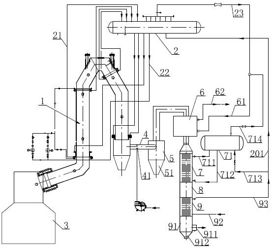
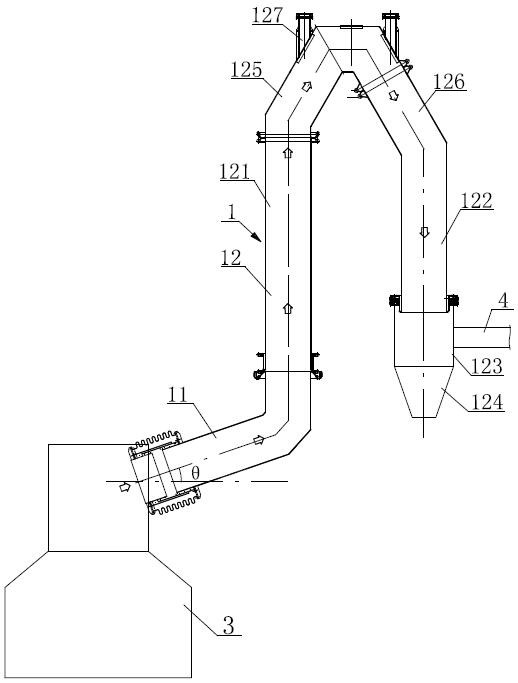
[0019] like figure 1 , figure 2 As shown in the figure, the waste heat recovery system matched with the HISMELT smelting reduction ironmaking system includes: the cooling flue 1 of the membrane water wall structure, the flue water wall riser 21 of the membrane water wall of the cooling flue 1, and the flue water cooling The wall downpipe 22 is connected to the flue drum 2 . The cooling flue 1 includes the cooling flue 11 in the inlet section, the cooling flue 11 in the inlet section is connected with the reaction furnace 3, the cooling flue 11 in the inlet section is gradually inclined upward from the reaction furnace 3, and the cooling flue 11 in the inlet section is arranged in a horizontal direction. The angle θ is greater than or equal to 45 degrees and less than or equal to 60 degrees. The molten slag in the high-temperature fl...


PUM


Abstract

The invention discloses a waste heat recovery system matched with an HISMELT smelting reduction ironmaking system. The waste heat recovery system comprises a cooling flue and a flue steam pocket, the outlet end of the cooling flue is provided with a connecting flue, the outlet of the connecting flue is connected to a separator, the inlet section of the cooling flue is connected to a reacting furnace, and a cooling medium is introduced into the connecting flue to cool flue gas; a smoke outlet of the separator is connected with a steam superheater, a superheater smoke outlet of the steam superheater is connected with a fire-tube boiler, a boiler ascending tube and a boiler descending tube of the fire-tube boiler are connected to a boiler drum, the fire-tube boiler is connected with a fire-tube economizer, and a smoke exhaust barrel is arranged at the bottom of the fire-tube economizer. An economizer water outlet pipe on the fire tube economizer supplies water to the fire tube boiler drum and the flue drum, steam output by the flue drum and the fire tube boiler drum is conveyed to the steam superheater, and a superheated steam output pipe is arranged on the steam superheater. The slag-bonding phenomenon can be effectively avoided, and the heat efficiency is greatly improved.

Description

technical field [0001] The invention relates to a waste heat recovery system, in particular to a waste heat recovery system matched with a HISMELT smelting reduction ironmaking system. Background technique [0002] HISMELT smelting reduction ironmaking technology is a short-process ironmaking technology that uses non-coking coal and iron ore powder to produce liquid iron by injection. Because it does not need the coke process and pellet process of the original iron making, and directly uses coal powder and iron ore powder to make iron, it has the advantages of strong adaptability of raw materials, low environmental pollution, and high product quality, and the construction of the factory is relatively simple. It has high social, economic and environmental value. The smelting reduction ironmaking technology is a technical improvement in the blast furnace ironmaking technology, and the waste heat recovery system is a key part of the whole system. [0003] The HISMELT reaction...

Claims


Application Information

Patent Timeline
Patent Type & Authority Applications(China)
IPC IPC(8): F27D17/00
CPCF27D17/004F27D17/008
Inventor 钱飞舟朱泓魏兆强
Owner SUZHOU HAILU HEAVY IND
Why Eureka
Try Eureka