
Method for producing marine fuel oil

A technology for fuel oil and marine use, which is applied in the field of flexible production of low-sulfur marine fuel oil. It can solve the problems of increased difficulty in product blending, increased production costs, and improved conversion rates, and achieves improved metal capacity, low energy consumption of devices, and enhanced adaptability. sexual effect

Active Publication Date: 2022-06-21
CHINA PETROLEUM & CHEM CORP +1
View PDF6 Cites 0 Cited by
  • Summary
  • Abstract
  • Description
  • Claims
  • Application Information

AI Technical Summary

Problems solved by technology

Along the direction of the liquid phase flow, the reaction temperature gradually increases. The disadvantage of this route is that the hydrogen consumption is high during the hydrogenation process and the amount of hydrogenation is large. Usually, when the sulfur content meets the index, a higher reaction severity is required. Under the condition of high temperature and high pressure, the sulfur content meets the requirements of the indicators, and other indicators such as carbon residues are greatly reduced, the conversion rate is increased, and the processing cost is high.
This method needs to use the conventional residual oil hydrogenation process to reduce the sulfur in the residual oil raw material to less than 1500 wppm. However, due to the substantial increase in production costs due to the addition of a large proportion of diesel and other fractions, it still cannot overcome the poor quality of the conventional residual oil hydrogenation process. The production cycle of residual oil raw materials is short, the difficulty of product reconciliation increases, the process is complicated, and the economy is poor

Method used


Image

  • Method for producing marine fuel oil
  • Method for producing marine fuel oil

Examples


Embodiment 1

[0041] The fixed bed reactor of the device adopts three sets in series, one of which is filled with two kinds of residual oil hydrogenation protection agents, and the filling volume is 12mL of FZC-12B catalyst and 45mL of FZC-103E catalyst; Catalysts, the loading volume is 60mL for FZC-28A catalyst and 165mL for FZC-204 catalyst; FZC-34A, a residual oil hydrodesulfurization catalyst, is loaded in the three reverse reactions, and the loading volume is 220mL. Catalyst properties are shown in Table 2.

[0042] The upflow reactor of the device adopts one reactor with two beds, of which the first bed is filled with 40mL of FZC-10U upflow residual oil hydrodemetallation catalyst, and the second bed is filled with FZC-11U upflow residual oil demetallization catalyst. Hydrogen desulfurization catalyst 47mL, a total of 87mL filled. Catalyst properties are shown in Table 3.

[0043] After further hydrogenation treatment, fixed bed hydrogenation reaction produces oil. The main operati...

Embodiment 2

[0047] The upflow reactor of the device adopts one reactor with two beds, of which the first bed is filled with FZC-10U upflow residual oil hydrodemetallation catalyst 170mL, and the second bed is filled with FZC-11U upflow residual oil demetallization catalyst. Hydrogen desulfurization catalyst 169mL, a total of 339mL filled. Catalyst properties are shown in Table 3.

[0048] After further hydrogenation treatment, fixed bed hydrogenation reaction produces oil. The main operating conditions are shown in Table 4, and the properties of the reaction product are shown in Table 5.

[0049] Raw material A is mixed with the effluent of the upflow hydrogenation reactor and circulating hydrogen, and then undergoes hydrogenation treatment in a fixed bed hydrogenation reactor, and then undergoes gas-liquid separation to obtain gas-phase products and liquid-phase products, wherein the liquid-phase products are subjected to atmospheric fractionation to obtain fuel gas , hydrogenated naph...

Embodiment 3

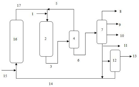
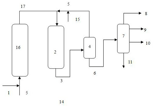
This comparative example adopts the process route of upflow type and fixed bed reactor series (see figure 2 ), that is, the residual oil raw material is first hydrogenated in the upflow reactor, and then enters the fixed bed reactor for hydrogenation reaction, and the hydrogenated oil is fractionated to obtain fuel gas, hydrogenated naphtha, hydrogenated diesel and hydrogenated Atmospheric residue. Hydrogenated atmospheric residual oil is used as a low-sulfur marine fuel product.

[0054] The upflow reactor of the device adopts one reactor with two beds, of which the first bed is filled with 80mL FZC-10U upflow residual oil hydrodemetallation catalyst, and the second bed is filled with FZC-11U upflow residual oil demetallization catalyst. Hydrogen desulfurization catalyst 89mL, a total of 169mL filled. Catalyst properties are shown in Table 3.

[0055] The fixed-bed reactor of the device adopts three sets in series, one of which is filled with three kinds of residual oil hy...


PUM


Abstract

The invention discloses a method for producing low-sulfur marine fuel oil. The method comprises the following steps: (1) mixing a residual oil raw material with an up-flow hydrogenation reactor effluent obtained in step (3) and hydrogen, and feeding the mixture into a fixed bed hydrogenation unit for a first hydrofining reaction to obtain hydrogenated oil; (2) carrying out normal-pressure fractionation on the hydrogenated oil to obtain hydrogenated normal-pressure residual oil, hydrogenated naphtha and hydrogenated diesel oil; partial hydrogenated atmospheric pressure residual oil is subjected to vacuum fractionation to obtain hydrogenated vacuum residual oil and hydrogenated vacuum wax oil; (3) mixing the hydrogenation vacuum residual oil with hydrogen, feeding the mixture into an up-flow hydrogenation reactor, and carrying out a second hydrofining reaction to obtain an up-flow hydrogenation reactor effluent; and (4) mixing part of the hydrogenated atmospheric pressure residual oil with at least part of the hydrogenated vacuum wax oil to obtain the marine fuel oil product. When the method is used for treating the inferior residual oil raw material, the low-sulfur marine fuel oil product which meets the index requirements of sulfur content, viscosity and the like of the product and has a stable peptizing system can be obtained.

Description

technical field [0001] The invention relates to a process method for producing clean fuel oil from inferior residual oil, in particular to a process method for flexibly producing low-sulfur marine fuel oil by using inferior high-sulfur residual oil as raw material. Background technique [0002] With the increasingly stringent global environmental protection regulations, clean low-sulfur marine fuel oil will become one of the key oil products in the next few years after the upgrading of clean gasoline and diesel and other light oil products. The International Maritime Organization (IMO) "International Convention for the Prevention of Pollution from Ships" stipulates that from January 2020, the sulfur mass fraction of marine fuel oil used for navigation in general areas of the sea will be reduced from the current not more than 3.5% to not more than 0.5%; when navigating in emission control areas, the sulfur content of marine fuel oil should not exceed 0.1%. In the marine fuel...

Claims


Application Information

Patent Timeline
Patent Type & Authority Applications(China)
IPC IPC(8): C10G67/02
CPCC10G67/02C10G2300/202C10G2300/302C10G2300/205C10G2300/201C10G2300/70C10G2300/1077C10G2300/4006C10G2300/4012C10G2300/4018C10G2300/308Y02P30/20
Inventor 刘铁斌韩坤鹏金建辉耿新国
Owner CHINA PETROLEUM & CHEM CORP
Learn More