
Portable high-precision automatic feeding drilling equipment

An automatic feed drilling, high-precision technology, applied in the direction of drilling/drilling equipment, feeding device, positioning device, etc., can solve the problems of fixed transmission ratio, inability to change processing parameters, high price, etc.

Pending Publication Date: 2022-07-12
DALIAN UNIV OF TECH
View PDF11 Cites 0 Cited by
  • Summary
  • Abstract
  • Description
  • Claims
  • Application Information

AI Technical Summary

Problems solved by technology

[0003] The research work on portable automatic hole-making equipment has been carried out earlier in foreign countries. At present, there are many automatic feed drilling products of many companies on the market. For example, Jeremy Dean Watford and others from the French APEX company invented "Feed OscillationVia Variable Pitch Gears". No. ZL 14 / 990,042, the invention adopts the air motor drive mode, and the power is output to the main shaft through the gear transmission, so as to realize the fixed rotation speed and feed speed. The ratio is fixed, and the processing parameters cannot be changed during the drilling process
Sebastian Pereira of France's Seti Technology Company invented "drilling device with automatic or controlled feed rate with self-aligning spindle", the patent number is ZL201710628905.7, and the device is driven by dual motors mode, the main motor and the auxiliary motor independently control the rotary motion and feed motion of the drilling rig, the gear set has a compact structure, and the precision of the parts is high. The main shaft structure is processed by a special process, which makes the price extremely expensive. The accuracy and stability are also difficult to meet the requirements, which seriously limits its wide application
Wang Fuji and others from Dalian University of Technology invented "a portable semi-automatic hole-making equipment and hole-making method". The patent number is ZL 202010441887.3. The device adopts a dual-motor drive mode. It can realize stepless speed change and change process parameters, and can install an axial low-frequency vibration auxiliary module to realize the chip breaking function of difficult-to-machine metal materials. Large and difficult to guarantee motion accuracy, it is difficult to meet the needs of narrow space and high-precision hole making

Method used


Image

  • Portable high-precision automatic feeding drilling equipment
  • Portable high-precision automatic feeding drilling equipment
  • Portable high-precision automatic feeding drilling equipment

Examples


Embodiment 1

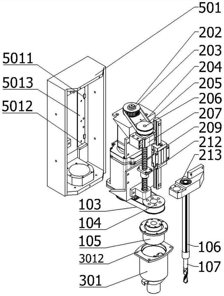
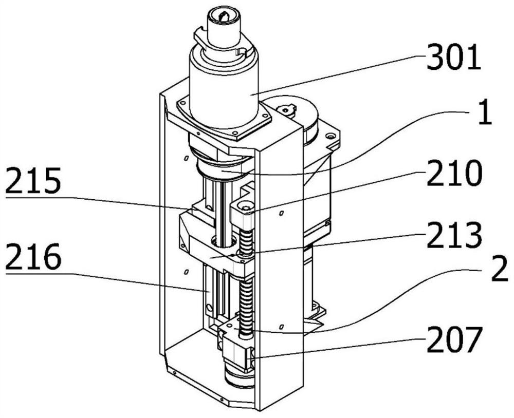
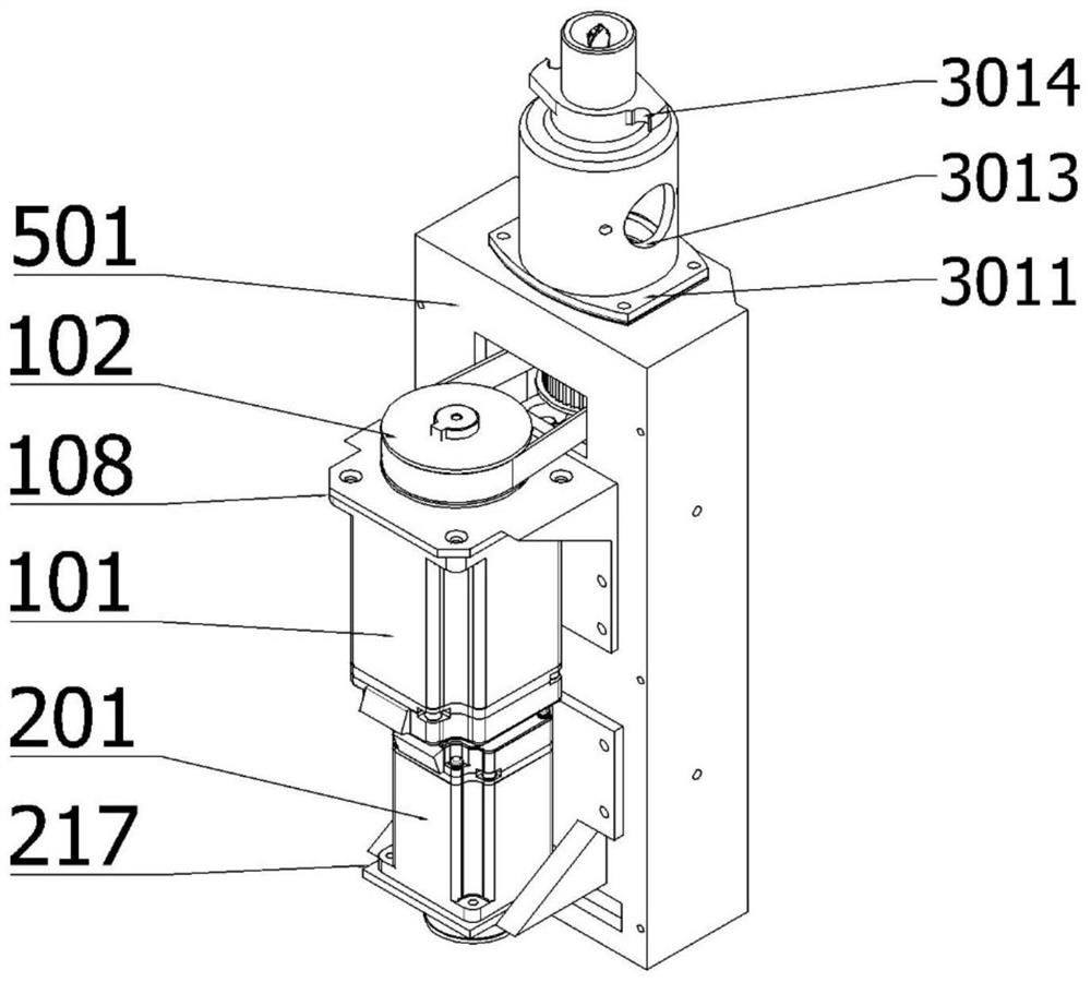
[0030] refer to Figure 1 to Figure 7 , a portable high-precision automatic feeding drilling equipment, including: a spindle module 1, a feeding module 2, a drill body fixing module 3, a control module 4 and a load-bearing frame.

[0031] In this embodiment, the spindle motor base 108 of the spindle module 1 is connected to the spindle motor 101 through bolts. The spindle motor 101 is a power source, and the spindle motor 101 and the spindle timing pulley 102 are tightly connected, and the spindle timing belt 103 is used to synchronize the spindle. The pulley 102 is connected to the spline timing pulley 104 . The spline timing pulley 104 is fastened to one end of the ball spline nut 105 by bolts, and the other end of the ball spline nut 105 is fitted into the mounting hole of the housing 501 . The ball spline nut 105 is divided into two parts: the outer stator and the inner rotor. The inner rotor part has ball grooves. The power is transmitted to the spline spindle 106 throug...


PUM


Abstract

The invention belongs to the field of machining equipment, and provides portable high-precision automatic feeding drilling equipment which comprises a main shaft module, a feeding module, a drill body fixing module, a control module and a bearing frame. Wherein the spindle module comprises a spindle motor, a spindle belt pulley transmission device, a spline spindle and a special drill bit and is used for driving rotary cutting motion of the drill bit; the feeding module comprises a power unit and a positioning unit and is used for driving the high-precision feeding movement of the drill bit; the drill body fixing module is used for quickly and stably clamping an automatic feeding drill and a workpiece material; and the control module is used for controlling drilling parameters, feeding distance and starting and stopping. According to the invention, the two independent motors are used for simultaneously realizing the rotating motion and the feeding motion of the main shaft, and the drilling parameters can be changed in the drilling process, so that the characteristics of different materials are well matched; the drilling equipment can be used for quickly and stably clamping, the drilling efficiency and the drilling precision stability are ensured, and the intelligent degree is high.

Description

technical field [0001] The invention relates to the field of processing equipment, in particular to a portable high-precision automatic feeding drilling equipment. Background technique [0002] Lightweight and high-strength carbon fiber reinforced resin matrix composites (CFRP) and metal materials resistant to alternating loads (such as titanium alloys, aluminum alloys, etc.) are the best choices for weight reduction and efficiency enhancement of high-end aerospace equipment. In order to ensure the highly reliable assembly and high-performance service of CFRP and laminated structures, tens of thousands of high-precision, high-surface-quality connection holes must be processed efficiently. Due to the fact that most of the holes are made at the assembly site, the space is limited, and the processing accessibility of traditional CNC machine tools and industrial robotic arms is poor and difficult to apply; manual processing has to be used as a last resort, and the axial force of...

Claims


Application Information

Patent Timeline
IPC IPC(8): B23B47/00B23B47/28B23B49/02B23Q3/06B23Q5/22B23Q5/40
CPCB23B47/00B23Q5/22B23Q5/40B23Q3/06B23B47/28B23B49/02Y02P70/10
Inventor 付饶刘帅王福吉李泳坤常宇豪赵猛张博宇
Owner DALIAN UNIV OF TECH
Learn More