Alloy powder sleeve cutter and alloy filling method thereof
A technology of alloy powder and knife set, which is applied in the direction of metal processing equipment, metal material coating technology, manufacturing tools, etc., can solve the problems of unsatisfactory wear resistance, hardness and wear resistance, and lasting sharpness. Low hardness and other problems, to achieve good lasting sharpness, ensure vertical and horizontal uniformity, and increase wear resistance
- Summary
- Abstract
- Description
- Claims
- Application Information
AI Technical Summary
Problems solved by technology
Method used
Image
Examples
Embodiment 1
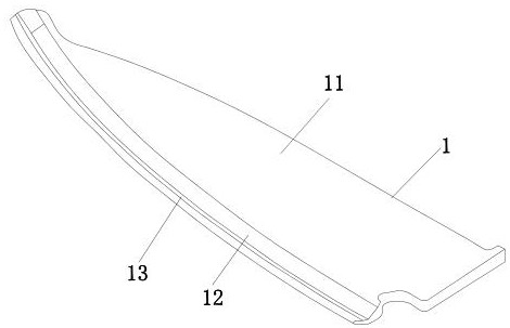
[0035] Alloy filling method of alloy powder set knife: make the knife body, the knife body has a knife body and a knife edge; use CNC to make grooves on the edge of one side of the knife edge, and use a laser beam to act on one side of the knife blank. There is a filling groove on the side, and the filling groove has an arc; the powder feeder is used to send the alloy powder to the filling groove. The inner diameter of the powder outlet of the nozzle of the powder feeder is 1.1mm, the inner diameter of the restraint auxiliary gas pipe is 5mm, and the inner diameter of the outermost protective gas pipe is 5mm. It is 9mm, the carrier gas of the alloy powder, the nozzle powder beam gathering gas and the outer protective gas are all helium gas, the protective gas flow rate is 14L / min, and the nozzle angle is 40 degrees. The effect of restraining the powder beam makes the nozzle powder have a good restraint length and necessary stiffness when it is ejected. Laser cladding is carried...
Embodiment 2
[0037] Alloy filling method of alloy powder set knife: make the knife body, the knife body has a knife body and a knife edge; use CNC to make grooves on the edge of one side of the knife edge, and use a laser beam to act on one side of the knife blank. There is a filling groove on the side, and the filling groove has an arc; the powder feeder is used to send the alloy powder to the filling groove. The inner diameter of the powder discharge nozzle of the powder feeder is 1.2mm, the inner diameter of the restraint auxiliary air pipe is 5mm, and the inner diameter of the outermost protective air pipe is 5mm. It is 9.5mm, the carrier gas of the alloy powder, the nozzle powder beam gathering gas and the outer protective gas are all helium gas, the protective gas flow rate is 15L / min, and the nozzle angle is 42 degrees. To the effect of restraining the powder beam, the nozzle powder has a good restraint length and necessary stiffness when it is ejected. Laser cladding is performed at...
Embodiment 3
[0039]Alloy filling method of alloy powder set knife: make the knife body, the knife body has a knife body and a knife edge; use CNC to make grooves on the edge of one side of the knife edge, and use a laser beam to act on one side of the knife blank. There is a filling groove on the side, and the filling groove has an arc; the powder feeder is used to send the alloy powder to the filling groove. The inner diameter of the powder outlet of the nozzle of the powder feeder is 1.14mm, the inner diameter of the restraint auxiliary gas pipe is 5.5mm, and the outermost protective gas pipe The inner diameter is 9.3mm, the carrier gas of the alloy powder, the nozzle powder beam gathering gas and the outer protective gas are all helium gas, the protective gas flow rate is 14.5L / min, and the nozzle angle is 43 degrees. , plays the role of restraining the powder beam, so that the nozzle powder has a good restraint length and necessary stiffness when it is ejected. Laser cladding is perform...
PUM
 Abstract
Description
Claims
Application Information
 - R&D
- Intellectual Property
- Life Sciences
- Materials
- Tech Scout
- Unparalleled Data Quality
- Higher Quality Content
- 60% Fewer Hallucinations
Browse by: Latest US Patents, China's latest patents, Technical Efficacy Thesaurus, Application Domain, Technology Topic, Popular Technical Reports.
© 2025 PatSnap. All rights reserved.Legal|Privacy policy|Modern Slavery Act Transparency Statement|Sitemap|About US| Contact US: help@patsnap.com


