Wafer level packaging method and packaging structure

A wafer-level packaging and wafer technology, which is applied in the direction of semiconductor/solid-state device parts, semiconductor devices, electrical components, etc., to achieve the effect of simplifying the packaging method, avoiding long electroplating time, and taking into account electroplating efficiency and electroplating yield

Pending Publication Date: 2022-07-29
NINGBO SEMICON INT CORP
View PDF0 Cites 2 Cited by
  • Summary
  • Abstract
  • Description
  • Claims
  • Application Information

AI Technical Summary

Problems solved by technology

[0005] However, the current WLP method needs to be further simplified

Method used


Image

  • Wafer level packaging method and packaging structure
  • Wafer level packaging method and packaging structure
  • Wafer level packaging method and packaging structure

Examples


Embodiment 2

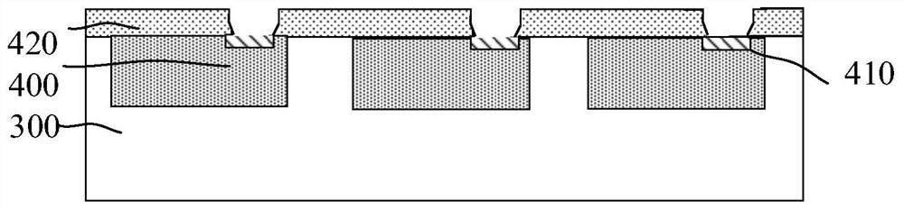
[0109] refer to Figure 9 , and the difference from the first embodiment is that a fourth pad 16 is formed on the other side of the first wafer 300 away from the second chip. During the electroplating process, a second conductive pad 16 is formed on the fourth pad 16 . Bump 80.

[0110] The exposed area of ​​the fourth pad is 5-200 square microns. Within this range, the pad can be in sufficient contact with the electroplating solution to avoid insufficient contact between the pad and the electroplating solution and affect the conductive bumps and pads. For example, the contact area is too small to affect the resistance, or the inability to contact causes poor electrical contact.

[0111] Circuits are also formed in the first wafer 300, and the circuits are connected to the fourth pads through wiring layers or plugs, and the second conductive bumps 80 shown are used to connect external circuits. Alternatively, there is a TSV structure in the first wafer 300 as shown, the firs...

Embodiment 3

[0113] refer to Figure 10 , in the above embodiments of the present invention, the first chip is only bonded on one side of the first wafer, that is, the top surface. In the fifth embodiment of the present invention, it may be on the front side of the first wafer The first chip is bonded, the back side is also bonded to the first chip, a first gap is formed between the second pad on the first chip and the first pad on the front side of the first wafer, and the first pad on the back side of the first chip A first gap is formed between the pad and the fourth pad on the back of the first wafer. During the electroplating process, the first chip and the first wafer on the front side and the first chip on the back side and the first wafer are simultaneously formed. Conductive bumps 310 are formed therebetween. The electroplating process formed by the conductive bumps 310 on the front and the back can be performed simultaneously or separately; the first die bonding process on the f...

Embodiment 4

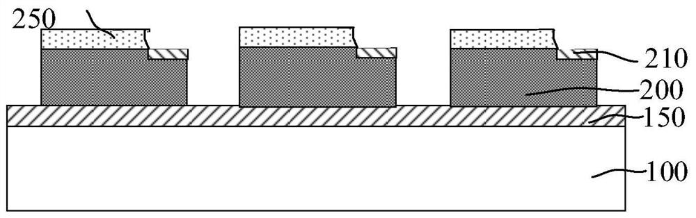
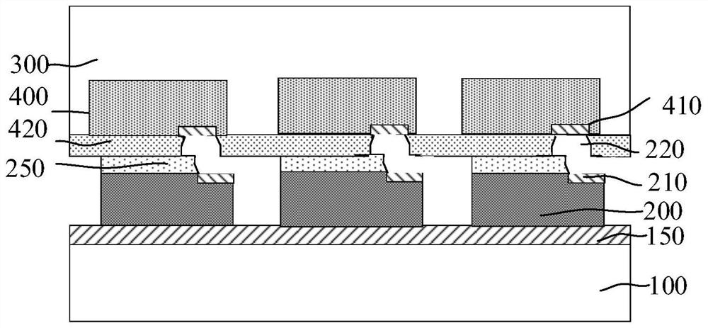
[0116] refer to Figure 11 In the sixth embodiment, a fifth pad 220 is formed on the other side of the second chip 200. After the second chip 200 is bonded on the first wafer, a third bonding pad 220 can be bonded on the second chip 30. The chip 501 can be bonded by a photolithographic bonding material, such as dry film; the third chip 501 includes a sixth pad 510, and a second gap is formed between the fifth pad and the sixth pad ; A third conductive bump 312 is formed in the second void by an electroplating process.

[0117] The fifth pad 220 and the second pad 210 are electrically connected through an interconnection structure. In this embodiment, the interconnection structure shown is a plug. In other embodiments, the interconnect structures shown may also be plugs and interconnect lines or pads.

[0118] The process of forming the third conductive bumps 312 may be the same as the forming process of forming the first conductive bumps 310 .

[0119] In this embodiment, t...


PUM

PropertyMeasurementUnit
thicknessaaaaaaaaaa
heightaaaaaaaaaa
areaaaaaaaaaaa

Abstract

The invention provides a wafer level packaging method and a packaging structure, and the method comprises the steps: providing a first wafer, forming a plurality of first chips in the first wafer, enabling the surface of each first chip to be provided with a first welding pad, and enabling the surface of the first wafer to be provided with a first dielectric layer which exposes the first welding pad; a plurality of second chips are provided, the surfaces of the second chips are provided with second welding pads, and second dielectric layers exposing the second welding pads are formed on the second chips; the second dielectric layer and the first dielectric layer are oppositely arranged, so that the second chip is bonded to the first wafer, the position of the second chip corresponds to the position of the first chip, and a first gap is formed between the first welding pad and the second welding pad; forming a first conductive bump for electrically connecting the first bonding pad and the second bonding pad in the first gap; and forming a packaging layer covering the second chip. According to the invention, the packaging process is simplified.

Description

technical field [0001] The present invention relates to the technical field of semiconductors, and in particular, to a wafer-level packaging method and a packaging structure. Background technique [0002] With the development trend of VLSI, the feature size of integrated circuits continues to decrease, and people's requirements for the packaging technology of integrated circuits continue to increase accordingly. Existing packaging technologies include Ball Grid Array (BGA), Chip Scale Package (CSP), Wafer Level Package (WLP), 3D Packaging (3D) and System in Package (System in Package). Package, SiP) etc. [0003] At present, in order to meet the goals of lower cost, more reliability, faster and higher density of integrated circuit packaging, advanced packaging methods mainly adopt Wafer Level Package System in Package (WLPSiP). Compared with the traditional system packaging, the wafer-level system packaging is to complete the packaging integration process on the wafer, whi...

Claims


Application Information

Patent Timeline
Patent Type & Authority Applications(China)
IPC IPC(8): H01L21/50H01L21/60H01L23/488H01L25/18H01L23/31
CPCH01L21/50H01L24/11H01L24/16H01L24/81H01L24/94H01L25/18H01L23/3107H01L2224/11462H01L2224/119H01L2224/16135H01L2224/16145H01L2224/18
Inventor 黄河向阳辉刘孟彬
Owner NINGBO SEMICON INT CORP
Why Eureka
Try Eureka