Pyrolysis gas heat recovery device and method for reducing tower diameter of gasoline fractionating tower

A heat recovery device and heat recovery technology, applied in the field of ethylene industry, can solve the problems of high manufacturing and transportation costs of large-scale equipment, incomplete heat recovery technology of pyrolysis gas, reduction of diameter of gasoline fractionation tower, etc., to reduce the cost of large-scale equipment manufacturing and transportation costs, long-term stable operation of large-scale equipment manufacturing and transportation costs, and the effect of reducing tower diameter

Active Publication Date: 2022-08-02
CHINA PETROLEUM & CHEM CORP +1
View PDF3 Cites 0 Cited by
  • Summary
  • Abstract
  • Description
  • Claims
  • Application Information

AI Technical Summary

Problems solved by technology

[0007] In order to solve the problems of incomplete waste heat recovery technology of cracked gas and high cost of large-scale equipment manufacturing and transportation, the present invention develops a heat recovery device for cracked gas and a method for reducing the diameter of gasoline fractionation tower. The dew point of the gas is different, and the heat is recovered and sent to the gasoline fractionator and the quenching water tower respectively, thereby effectively reducing the diameter of the gasoline fractionator, which is of great and far-reaching significance to the stable operation of the ethylene plant and the reduction of large-scale equipment manufacturing and transportation costs

Method used


Image

  • Pyrolysis gas heat recovery device and method for reducing tower diameter of gasoline fractionating tower
  • Pyrolysis gas heat recovery device and method for reducing tower diameter of gasoline fractionating tower
  • Pyrolysis gas heat recovery device and method for reducing tower diameter of gasoline fractionating tower

Examples


Embodiment approach

[0062] According to a preferred embodiment of the present invention, the liquid raw material pyrolysis gas P-12 after heat recovery enters the bottom of the weight-removing tower E-15, and the quenching oil P-2 enters the top of the weight-removing tower E-15; In 15, the liquid raw material pyrolysis gas P-12 after heat recovery is in countercurrent contact with the quenching oil P-2, so that the liquid raw material pyrolysis gas P-12 after heat recovery is further cooled to T2, and then enters the gasoline fractionation tower E-11 bottom.

[0063] According to the present invention, steam P-25 can be introduced into the lower part of the weight-removing tower E-15 as a stripping medium, or no steam can be introduced.

[0064] The present invention will be further described below with reference to the accompanying drawings and embodiments. It should be understood that the specific embodiments described herein are only used to illustrate and explain the present invention, but ...

Embodiment 1

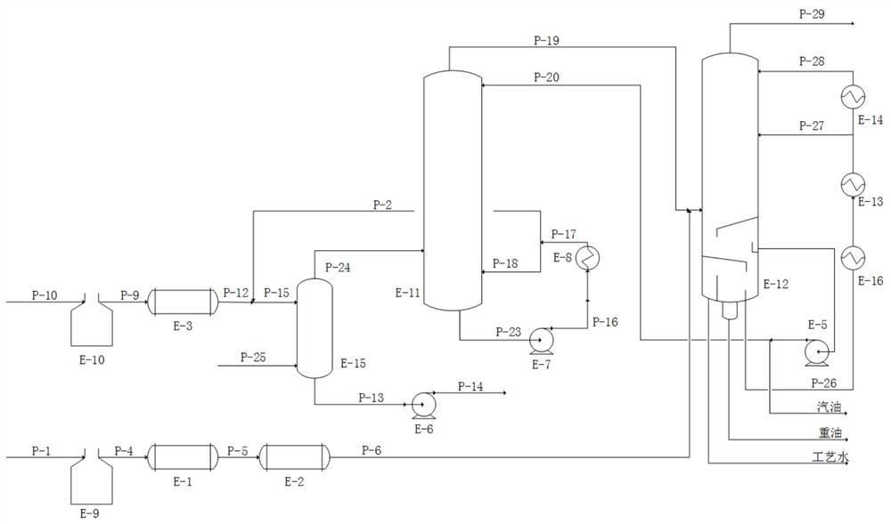
[0069] Example 1 uses as figure 1 Apparatus and process flow shown.

[0070] The device includes a liquid raw material pyrolysis gas heat recovery unit, a gas raw material pyrolysis gas heat recovery unit, a weight removal tower E-15, a gasoline fractionation tower E-11 and a quench water tower E-12.

[0071] The liquid raw material cracking gas heat recovery unit includes a liquid raw material cracking gas heat recovery facility E-3; the liquid raw material cracking gas heat recovery facility E-3 is connected to the discharge port of the liquid raw material cracking furnace E-10, and the liquid raw material cracking gas heat recovery facility E-3 is connected. The feed port of the raw material cracking furnace E-10 is connected with the liquid raw material pipeline.

[0072] The gas raw material cracking gas heat recovery unit includes a first heat recovery facility E-1 for the gas raw material cracking gas, a second heat recovery facility E-2 for the gas raw material cracki...

Embodiment 2

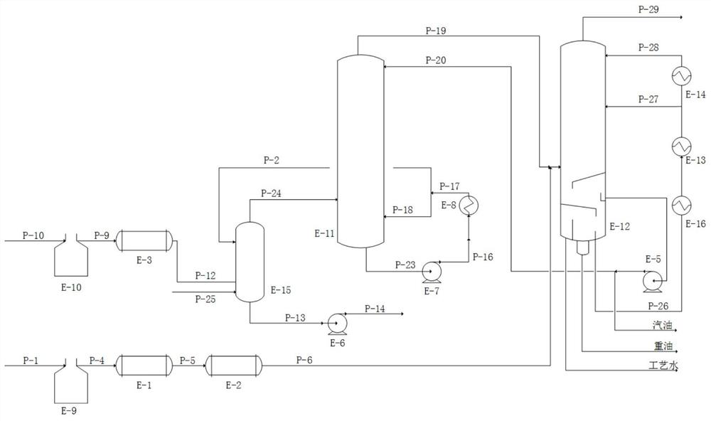
[0090] Embodiment 2 adopts as figure 2 Apparatus and process flow shown.

[0091] The device includes a liquid raw material pyrolysis gas heat recovery unit, a gas raw material pyrolysis gas heat recovery unit, a weight removal tower E-15, a gasoline fractionation tower E-11 and a quench water tower E-12.

[0092] The liquid raw material cracking gas heat recovery unit includes a liquid raw material cracking gas heat recovery facility E-3; the liquid raw material cracking gas heat recovery facility E-3 is connected to the discharge port of the liquid raw material cracking furnace E-10, and the liquid raw material cracking gas heat recovery facility E-3 is connected. The feed port of the raw material cracking furnace E-10 is connected with the liquid raw material pipeline.

[0093] The gas raw material cracking gas heat recovery unit includes a first heat recovery facility E-1 for the gas raw material cracking gas, a second heat recovery facility E-2 for the gas raw material ...


PUM

PropertyMeasurementUnit
diameteraaaaaaaaaa

Abstract

The invention belongs to the technical field of ethylene industry, and relates to a pyrolysis gas heat recovery device and a method for reducing the tower diameter of a gasoline fractionating tower. In the method, liquid raw material pyrolysis gas is cooled by a heat recovery facility, then mixed with a quenching material, cooled and then fed into a de-heavy tower, a tower top gas phase enters a gasoline fractionating tower for continuous cooling, part of components are condensed into liquid-phase quenching oil, and the liquid-phase quenching oil is pumped out by a pump, subjected to heat recovery and then divided into two streams, wherein one branch is used as a quenching medium to be mixed with the liquid raw material cracking gas subjected to heat recovery. The gas raw material pyrolysis gas is directly fed into a quenching water tower after heat recovery and is further mixed and cooled with pyrolysis gas from the top of a gasoline fractionating tower, and part of components are condensed into gasoline and heavy oil. In the method, the gas raw material pyrolysis gas directly enters the quenching water tower without passing through the gasoline fractionating tower after being cooled to a relatively low temperature through heat recovery, so that the tower diameter of the gasoline fractionating tower can be effectively reduced, heavy components in the liquid raw material pyrolysis gas are effectively removed, and the method has important significance on long-period stable operation of an ethylene device.

Description

technical field [0001] The invention belongs to the technical field of ethylene industry, and in particular relates to a pyrolysis gas heat recovery device and a method for reducing the diameter of a gasoline fractionation tower. Background technique [0002] The cracking raw materials of the ethylene plant include naphtha, diesel oil, hydrogenated tail oil, ethane, propane, LPG and other petrochemical raw materials. The energy consumption of the cracking process accounts for 50-60% of the entire plant. Energy saving and consumption reduction are of great significance. [0003] In the traditional process, the pyrolysis gas first goes through the waste heat boiler to recover high-grade heat energy and by-produces ultra-high pressure steam. The temperature of the liquid raw material pyrolysis gas after ultra-high pressure steam is generally 400-480 °C, and the temperature of some gas raw material pyrolysis gas after ultra-high pressure steam is generally The temperature is 35...

Claims


Application Information

Patent Timeline
Patent Type & Authority Applications(China)
IPC IPC(8): C10G55/00C07C4/04C07C11/04C10G5/06C10G7/00C10G7/12C10G9/00
CPCC10G9/002C10G5/06C10G55/00C10G7/00C10G7/12C07C4/04C07C11/04
Inventor 王振维赵百仁赵明瑞杨丽庆刘罡
Owner CHINA PETROLEUM & CHEM CORP
Why Eureka
Try Eureka