
Power semiconductor device and application thereof

A technology of power semiconductors and devices, which is applied in the field of power semiconductor devices, can solve the problems of affecting the efficiency of follower diodes, difficulty in design optimization, large occupied area, etc., and achieve good working performance and switching dynamic performance, high current density, and low leakage characteristics Effect

Pending Publication Date: 2022-08-09
SONGSHAN LAKE MATERIALS LAB +1
View PDF0 Cites 0 Cited by
  • Summary
  • Abstract
  • Description
  • Claims
  • Application Information

AI Technical Summary

Problems solved by technology

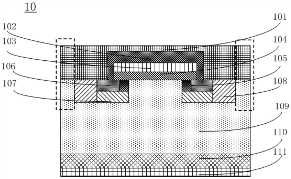
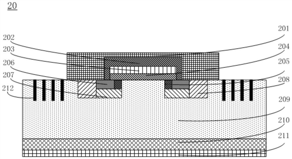
However, since the innermost standard floating field ring structure 212 is not electrically connected to the source 201, it does not participate in the conduction of the JBS freewheeling diode, thereby affecting the efficiency of the freewheeling diode, and because the standard floating field ring structure 212 itself acts as The terminal structure also occupies too much area (the width of the field ring terminal structure is usually more than 5 times the thickness of the drift layer), and the number and spacing of the standard floating field ring structures 212 are difficult to design and optimize in the manufacture of high-voltage devices.

Method used


Image

  • Power semiconductor device and application thereof
  • Power semiconductor device and application thereof
  • Power semiconductor device and application thereof

Examples


preparation example Construction

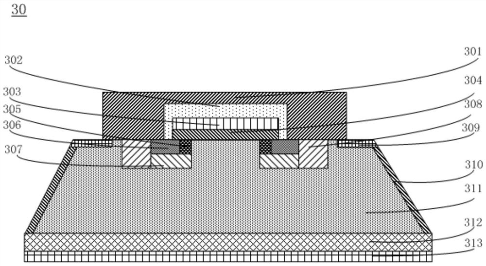
[0081] Further, the present invention also provides a method for manufacturing the power semiconductor device 30, which includes the following steps S110 to S160.

[0082] Step S110 : growing the drift region 311 on the substrate 312 by homoepitaxial growth.

[0083] Step S120 : forming the source region 306 , the well region 307 , and the base on the predetermined source region 306 , the well region 307 , the base region 308 and the channel region 305 on the side of the drift region 311 away from the substrate 312 region 308 and channel region 305 .

[0084] It can be understood that the predetermined source region 306 , well region 307 , base region 308 and channel region 305 can be vacated in the drift region 311 by etching but not limited to, and the positions of the source region 306 , the well region 307 , the base region 308 and the channel region 305 can be vacated by but not limited to high temperature ions. The implantation method forms the source region 306 , the w...

Embodiment 1

[0102] The present embodiment provides a power semiconductor device 30, and its preparation process is as follows:

[0103] S110, in the case of having the first conductivity type, the doping impurity is nitrogen or phosphorus, and the doping concentration is 10 19 / cm 3 ~5×10 19 / cm 3 , the Si surface of the silicon carbide substrate 312 with a thickness of 200 μm to 400 μm has the first conductivity type through homoepitaxial growth, and the doping impurity is nitrogen or phosphorus, and the doping concentration is 10 14 / cm 3 ~5×10 17 / cm 3 , a silicon carbide drift region 311 with a thickness of 5 μm to 200 μm;

[0104] S120, on the side of the silicon carbide drift region 311 away from the substrate 312, the material of the drift region 311 in the region where the source region 306 is located is removed by etching, and the material of the drift region 311 in the region where the source region 306 is located is formed by high temperature ion implantation to form a fi...


PUM

PropertyMeasurementUnit
Doping concentrationaaaaaaaaaa
Thicknessaaaaaaaaaa
Thicknessaaaaaaaaaa

Abstract

The invention discloses a power semiconductor device and application thereof, the device comprises a substrate, a source electrode and a drain electrode, the substrate is provided with a first surface and a second surface which are opposite to each other, a base electrode region, a source region, a channel region, a well region and a terminal region are arranged in the substrate, the terminal region comprises a first doped region and a second doped region, one side surfaces of the first doped region, the base region, the source region and the channel region are flush with the first surface of the substrate, the source is arranged on the first doped region, the base region, the source region and the first surface of the substrate, and the work function of the material of the substrate is smaller than that of the material of the source. The JBS free-wheeling diode is formed by the first doped region and the base region through the Schottky contact formed by the substrate between the first doped region and the base region and the source, the size of the device is reduced, the device has the characteristics of high terminal efficiency, high current density, high conduction characteristic, high voltage resistance and low electric leakage, and the device is suitable for large-scale production. And the switch has good working performance and switch dynamic performance in the first quadrant and the third quadrant.

Description

technical field [0001] The present invention relates to the technical field of semiconductor devices, in particular to a power semiconductor device and its application. Background technique [0002] A metal oxide semiconductor field effect power transistor (MOSFET) device generally refers to a vertical structure device formed on a substrate. Silicon carbide vertical power MOSFET devices can be mainly divided into double injection planar gate (MOSFET), trench vertical gate (VMOSFET) and U-shaped trench (UMOSFET). The etching and oxidation processes of silicon carbide trench MOSFETs are difficult. In order to protect the gate oxide, a P-type shielding layer needs to be added at the bottom of the trench, resulting in an increase in on-resistance. At this stage, the planar gate structure process is simpler, has better commercial yield and lower cost, and has certain advantages in the high-voltage market. [0003] Junction barrier Schottky diodes (JBS) combine the excellent swi...

Claims


Application Information

Patent Timeline
IPC IPC(8): H01L29/78H01L29/06
CPCH01L29/7806H01L29/0603Y02B70/10
Inventor 袁朝城夏经华张安平
Owner SONGSHAN LAKE MATERIALS LAB
Learn More