Laser processing method, mfg. of ink jetting recording head using said method, and the recording head therefrom

A laser processing method, laser beam technology, applied in the direction of laser welding equipment, metal processing equipment, manufacturing tools, etc.

Inactive Publication Date: 2004-07-21
CANON KK
View PDF2 Cites 1 Cited by
  • Summary
  • Abstract
  • Description
  • Claims
  • Application Information

AI Technical Summary

Problems solved by technology

[0019] However, when the processing pitch or the processing diameter becomes smaller, the observable phenomenon of the excimer laser processing as described above becomes more prominent, so the above-mentioned method is used to manufacture jets of the type with high precision as described above. Ink heads have certain limitations

Method used


Image

  • Laser processing method, mfg. of ink jetting recording head using said method, and the recording head therefrom
  • Laser processing method, mfg. of ink jetting recording head using said method, and the recording head therefrom
  • Laser processing method, mfg. of ink jetting recording head using said method, and the recording head therefrom

Examples


no. 1 example

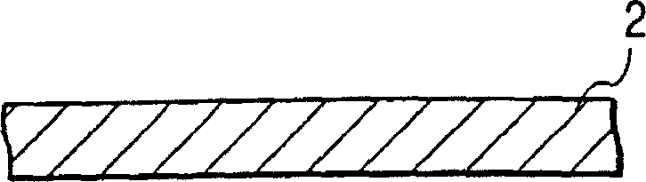
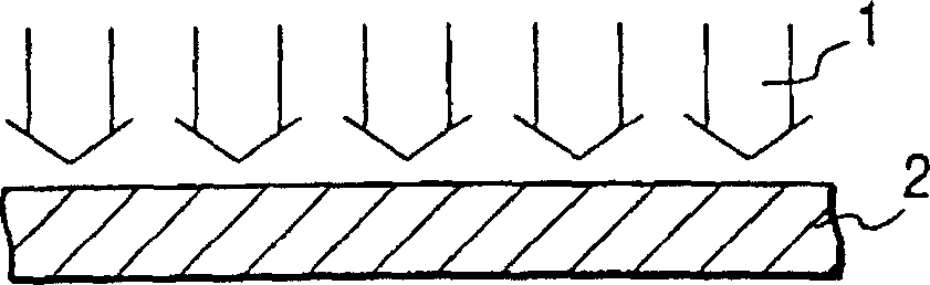
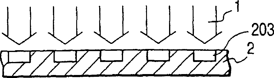
[0127] attached Figures 1A to 1E A method of processing the ink ejection ports of the ink jet recording head according to the first embodiment of the present invention is schematically illustrated. attached Figures 1A to 1E The course of the method is shown schematically in chronological order.

[0128] in the attached Figure 1A In , reference numeral 2 denotes a resin plate as a raw material for manufacturing the ink discharge port. as attached Figure 1B As shown, the laser beam 1 passes through a mask with a plurality of openings at predetermined intervals, and irradiates the resin plate 2 to form a structure with multiple discharge ports, so that the density of the discharge ports formed is 900 dpi. Here, according to this embodiment, the femtosecond laser is applied under the following conditions: the emitted laser beam is an infrared ray with a wavelength of 775nm; the emission pulse time amplitude is 150 femtoseconds per pulse; Energy density (fluence) is about 1...

Embodiment 2

[0159] attached Figures 4A to 4D And attached 5E to 5G A processing step of forming a cut by laser processing according to a second embodiment of the present invention is illustrated.

[0160] Now, according to the attached Figures 4A to 4D And attached 5E to 5G , a method of manufacturing an electrostatic notch is described.

[0161] in the attached Figure 4A In this, a base member is prepared in such a manner that an aluminum thin film 42 is formed on a silicon substrate 41 by using vapor deposition or sputtering. Then, a resin layer 43 (ie, a protective layer) is coated on the aluminum thin film layer 42 by using a spin coating method.

[0162] in the attached Figure 4B In the shown steps, the resin layer 43 is partially removed by irradiation of patterned laser light, and an electronic contact surface A is formed. Then, in the attached Figure 4C In the steps shown, a metal film 44 (ie, an elastic metal film such as aluminum or copper) is formed by vapor depo...

no. 3 example

[0167] attached Figures 6A to 6C Schematically illustrates the process of manufacturing ink jets by laser processing according to the third embodiment of the present invention.

[0168] The method for forming the ink ejection ports 40 of the ink jet recording head on the orifice plate 60 will be described with reference to the attached Figures 6A to 6C Be explained.

[0169] in the attached Figure 6A In , the orifice plate assembly is made by inserting a layer of copper foil 62 in a polysulfone plate 61 .

[0170] Due to the copper foil 62 inserted in the polysulfone board 61, the following effects can be achieved, wherein:

[0171] (1) The thermal expansion of the polysulfone plate can be made as close as possible to the thermal expansion of the silicon integrated circuit substrate 80, wherein the silicon top plate 70 constitutes the ink flow path, the ink chamber, and the like in the main body of the inkjet head, and includes the nozzle The ink pressure generating mem...


PUM

PropertyMeasurementUnit
wavelengthaaaaaaaaaa

Abstract

A laser processing method for performing laser ablation process on a work piece by radiating laser beam on the work piece includes the step of forming simultaneously a plurality of process shapes arranged at a predetermined interval by use of laser beam of plural pulses having extremely large spatial and temporal energy density radiated from a laser oscillator as the laser beam oscillating at the pulse radiation time of one picosecond or less. With the laser processing method thus structured, it is possible to perform a highly precise processing without creating by-product, as well as to fundamentally prevent the converted thermal energy from being accumulated on a work piece, such as resin, which causes the work piece to be fused or thermally expanded during the operation of laser processing.

Description

technical field [0001] The invention relates to a laser processing method. More specifically, the present invention relates to a manufacturing method using such laser processing, for example, manufacturing an ink jet recording head that makes ink droplets fly out and adhere to a recording medium, and, at the same time, to manufacturing inkjet recording head. Background technique [0002] Conventionally, there is known a laser processing method using an ultraviolet laser, which can be used to precisely process a structural member requiring minute structures formed with high precision. [0003] As an example of such precise processing, one of them may process an ink flow path or an ink ejection port of an ink jet head. [0004] In the specification of Japanese Laid-Open Patent Application No. 2-121842 or 2-121845, it is disclosed that an excimer laser, typically an ultraviolet laser, is used to process an ink flow path or an ink ejection port with high precision. [0005] I...

Claims


Application Information

Patent Timeline
Patent Type & Authority Patents(China)
IPC IPC(8): B41J2/005B23K26/06B23K26/40B41J2/15B41J2/16
CPCB41J2002/14379B41J2/1626B41J2/1634B23K26/4005B23K26/401B23K26/0635B41J2/1607B41J2/162B41J2/1623B23K26/0656B23K26/407B41J2002/14387B41J2/1601B41J2/15B23K26/4065B23K26/0624B23K26/066B23K26/40B23K2103/54B23K2103/08B23K2103/42B23K2103/50B41J2/005
Inventor 小出纯
Owner CANON KK
Why Eureka
Try Eureka