Self-melting adhered insulating wire and self-melting adhered twisted wire using same

An insulated wire, self-adhesive technology, applied in the direction of insulated cables, insulated conductors, electrode devices and related components, etc., can solve problems such as insufficient strength of the adhesive film, reduction of the amount of solvent in the adhesive layer, and unclear resin components. , to achieve the effect of reducing odor and problems in the working environment, excellent heat resistance, and reducing problems

Inactive Publication Date: 2004-11-24
KANEKA CORP
View PDF3 Cites 2 Cited by
  • Summary
  • Abstract
  • Description
  • Claims
  • Application Information

AI Technical Summary

Problems solved by technology

[0022] However, in the method described in JP-A-5-225831, since the resin component contained in the adhesive paint is not clear, it is not known whether the amount of solvent remaining in the adhesive layer can be reduced. Moreover, due to the self-adhesive insulated wire The strength of the adhesive film is insufficient, so the initial deformation becomes large
[0023] In order to reduce the amount of residual solvent, t...

Method used

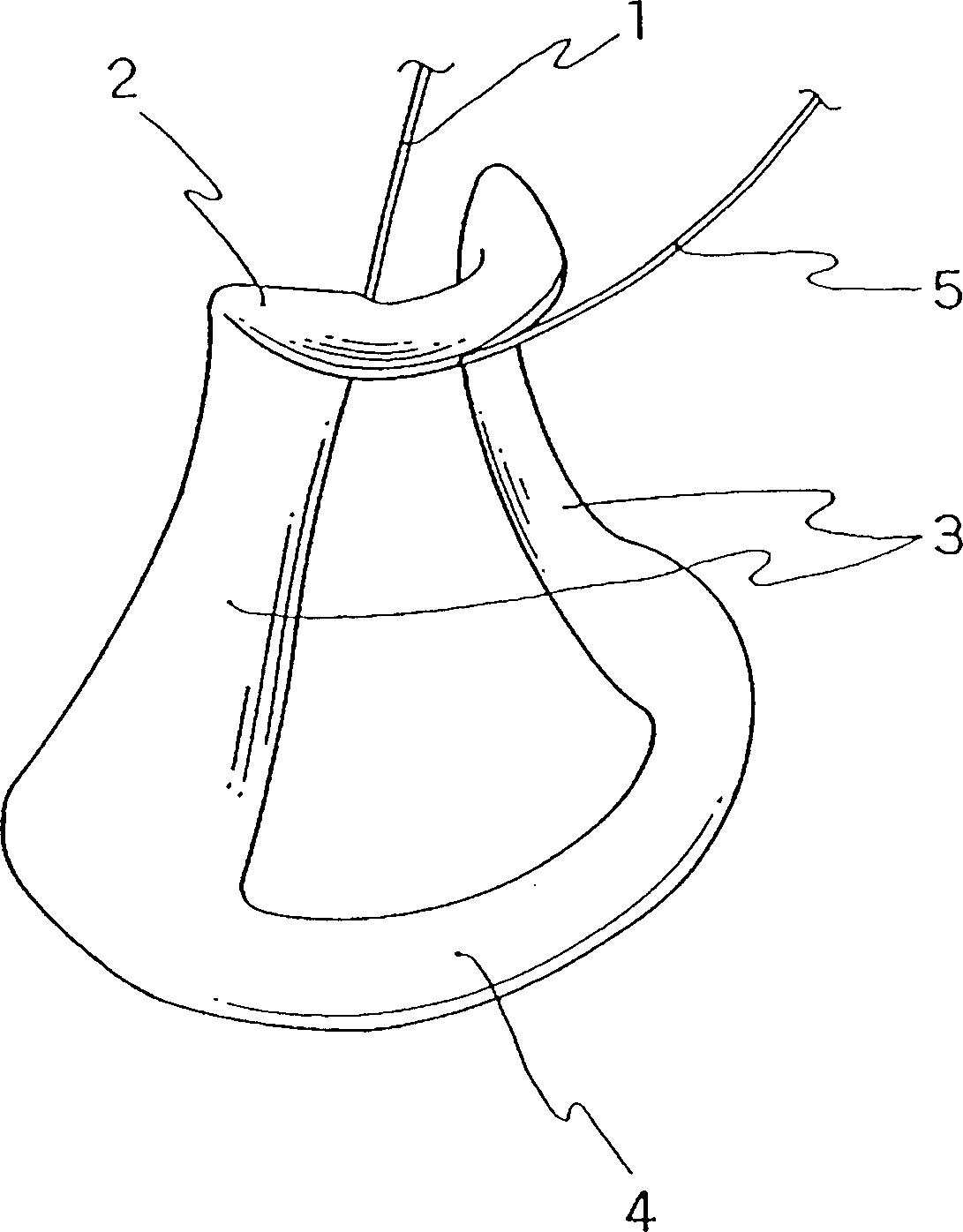
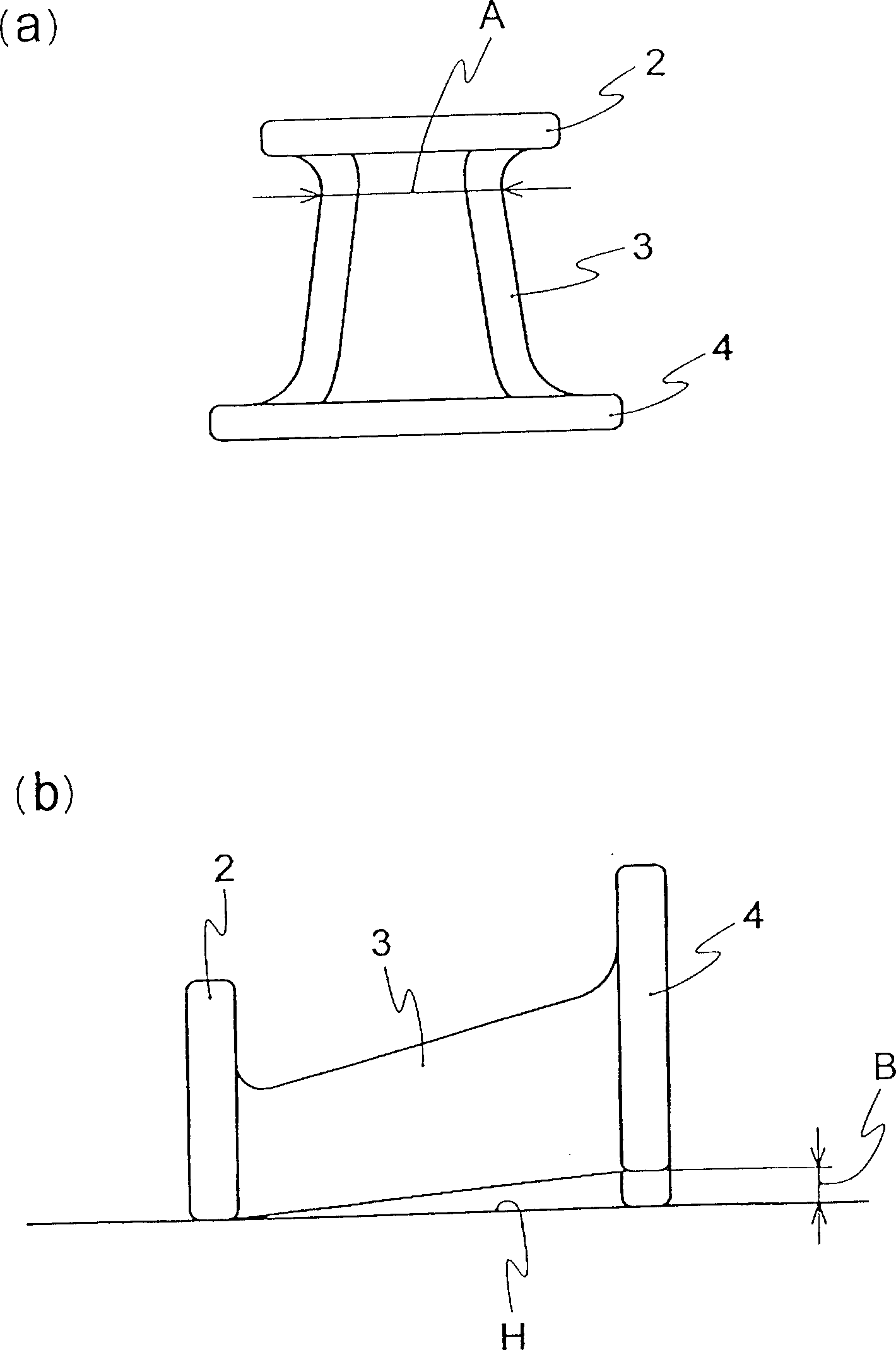
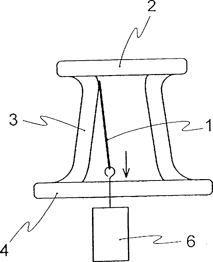

Image

  • Self-melting adhered insulating wire and self-melting adhered twisted wire using same
  • Self-melting adhered insulating wire and self-melting adhered twisted wire using same
  • Self-melting adhered insulating wire and self-melting adhered twisted wire using same

Examples


Embodiment 1

[0107] A crystalline copolyamide resin A (ε-caprolactam, ω-laurolactam, dodecanoic acid salt of hexamethylenediamine 3 Components, copolymers copolymerized at the above ratio) were dissolved in a mixed solvent of cresol and aromatic (C9) naphtha at a weight ratio of 70:30 to obtain an adhesive paint with a film component concentration of 19%. The viscosity of the obtained adhesive paint was 20 dPa·s at 30°C.

[0108] The obtained adhesive paint was repeatedly coated (coated by die drawing method) and baked (furnace length 3.0m, Oven temperature 300° C., wire speed 60 m / min), to obtain a self-adhesive insulated wire with an adhesive film thickness of 10 μm.

[0109]Twist 10 self-adhesive insulated wires obtained together to form a self-adhesive twisted wire, and then use the forming conditions to set 55 turns x 2 main coils, energize current 55A, energize time 1.5 seconds, cooling pressure machine for 15 seconds, and a metal mold temperature of 40°C, the self-adhesive twisted...

Embodiment 2

[0113] In addition to changing the crystalline copolyamide resin to a crystalline copolyamide resin with a melting point of 130°C, a relative viscosity of 1.42, and a crystallization energy of 44.8J / g B (ε-caprolactam, ω-laurolactam, hexamethylenediamine) Dodecanoic acid salt 3 kinds of components are copolymerized with the above-mentioned ratio), others are carried out in the same way as Example 1, and the results are shown in Table 2.

Embodiment 3

[0115] In addition to changing the crystalline copolyamide resin to crystalline copolyamide resin C (ε-caprolactam, ω-laurolactam, hexamethylenediamine) with a melting point of 130°C, a relative viscosity of 1.47, and a crystallization energy of 47.7J / g Dodecanoic acid salt 3 kinds of components are carried out in the same manner as Example 1 except that the copolymer is copolymerized at the above-mentioned ratio). The results are shown in Table 2.


PUM

PropertyMeasurementUnit
Melting pointaaaaaaaaaa
Relative viscosityaaaaaaaaaa

Abstract

A self-bonding insulated wire having a bonding layer on an insulated wire, the bonding layer comprising a crystalline copolyamide having a melting point within the range of 105 to 150 DEG C and a relative viscosity of 1.4 to 1.6 measured at 25 DEG C with respect to a 0.5% by weight m-cresol solution thereof, and optionally at least one member selected from the group consisting of a high-melting nylon having a melting point within the range of 200 to 300 DEG C and an antioxidant. The bonding layer can be formed from a coating having an increased resin concentration and the residual solvent content of the bonding layer is small. The self-bonding insulated wire and self-bonding litz wire comprised thereof provide deflecting coils having a decreased strain, good adhesive property and good heat resistance.

Description

technical field [0001] This invention relates to self-adhesive insulated wires and self-adhesive litz wires using the same in the manufacture of deflection choke coils for television receivers and computer displays. Background technique [0002] Self-adhesive insulated wire, since the outermost layer is provided with an adhesive layer, after the coil is wound in the mold, the outermost adhesive layer is dissolved or swelled by means of energized heating or solvent treatment, so that the wires It is obtained by bonding and curing each other, and self-supporting coils can be easily produced. In this way, the self-adhesive insulated wire can improve the productivity of electrical equipment coils and reduce manufacturing costs, so it will be widely used in household appliances, OA equipment, electrical equipment products, and deflection yokes for CRT displays. [0003] In recent years, CRT display devices have developed in the direction of miniaturization, heat resistance, high...

Claims


Application Information

Patent Timeline
IPC IPC(8): H01B7/02H01F5/06H01F27/28H01F27/32H01F41/06
CPCH01J2229/7035H01F27/2823H01F41/0616H01F5/06H01F27/323H01F41/065H01F41/066H01F41/071Y10T428/2933H01B7/02
Inventor 田村和重荒木寅盛永峰诚一
Owner KANEKA CORP
Why Eureka
Try Eureka