Fiber grating sensing and testing system for oil and gas pipeline detection
A fiber grating and testing system technology, which is applied in the direction of transmitting sensing components, pipeline systems, gas/liquid distribution and storage with optical devices, to achieve high test sensitivity, light weight, and simple structure
- Summary
- Abstract
- Description
- Claims
- Application Information
AI Technical Summary
Problems solved by technology
Method used
Image
Examples
Embodiment 1
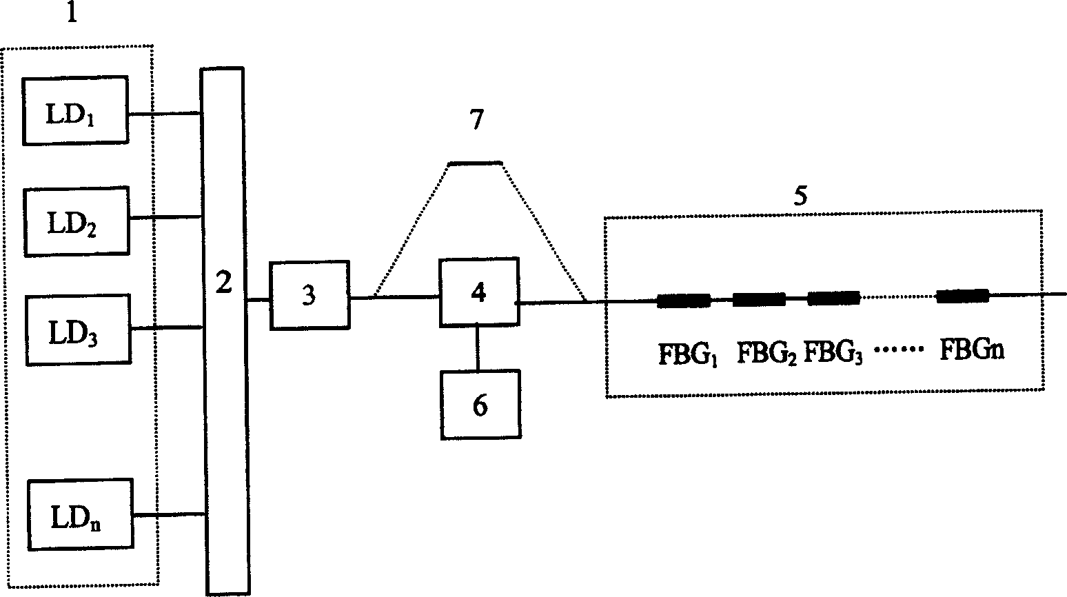
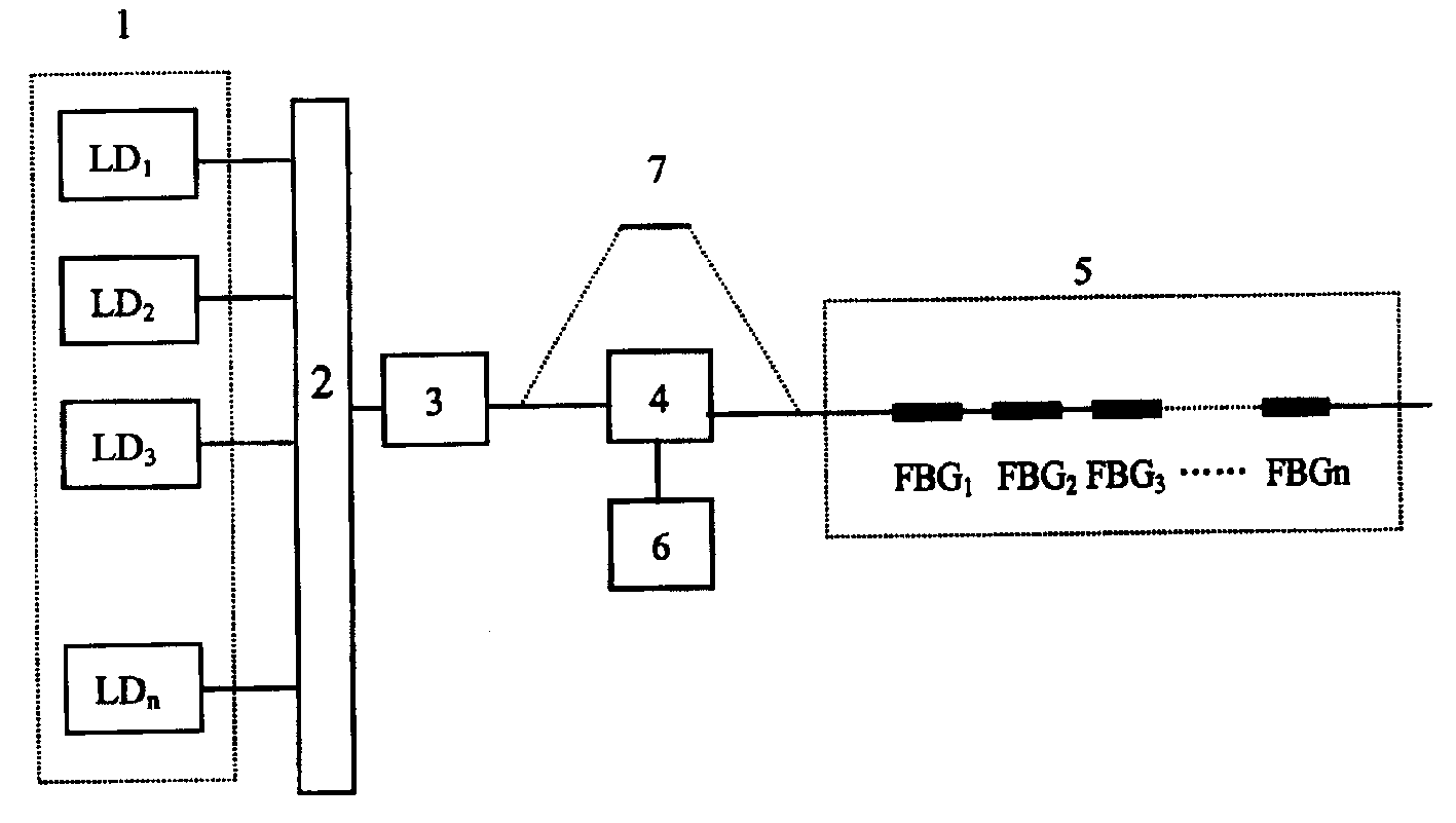
[0026] Example 1: Simultaneously measure the pressure at multiple points in a 3km long oil and gas pipeline.
[0027] The measurement length is 3km, and the distance between adjacent detection points is 20m, so there are 150 detection points, that is, 150 pressure fiber grating sensors with different coupling resonance wavelengths are selected, and the bandwidth of each fiber grating sensor is 2nm.
[0028] The output power of each broadband semiconductor laser SLD is 1mw, and the working wavelength bandwidth is 50nm. Each SLD center wavelength can cover 25 fiber grating sensors, so 6 SLDs with different center wavelengths are required, and the center wavelengths are λ 1 =1300nm, λ 2 =1350nm, λ 3 =1400nm, λ 4 =1450nm, λ 5 =1500nm, λ 6 =1550nm, the working wavelength range of the six SLD arrays is 1275nm~1575nm.
[0029] According to the central wavelength and bandwidth range of the broadband semiconductor laser SLD array 1, the coupling resonance wavelengths of all fiber ...
Embodiment 2
[0032] Example 2: Simultaneous and differentiated measurement of the temperature and pressure of a 2km long oil and gas pipeline
[0033] The measurement length is 2km, and the distance between adjacent detection points is 10m, so there are 200 detection points, that is, 100 temperature FBG sensors and 100 pressure FBG sensors with different coupling resonance wavelengths are selected, and the bandwidth of each FBG sensor is 2nm.
[0034] The output power of each broadband semiconductor laser SLD is 1mw, and the working wavelength bandwidth is 80nm. Each SLD center wavelength can cover 40 fiber grating sensors, so five SLDs with different center wavelengths are required, and the center wavelengths are λ 1 =1300nm, λ 2 =1380nm, λ 3 =1460nm, λ 4 =1540nm, λ 5 =1620nm, the working wavelength range of 5 SLD arrays is 1260nm~1660nm.
[0035] According to the central wavelength and bandwidth range of the broadband semiconductor laser SLD array 1, the coupling resonance wavelengths ...
Embodiment 3
[0037] Example 3: Simultaneous and differentiated measurement of the temperature and pressure of a 2km long oil and gas pipeline
[0038] The principle of this embodiment is the same as that of Embodiment 2,
[0039] The principle of this embodiment is the same as that of Embodiment 2, except that a temperature FBG sensor and a pressure FBG sensor are arranged near each detection point, and the distance between the two FBG sensors is 100 μm-400 μm.
[0040] The measurement length is 2km, and the distance between adjacent detection points is 20m, so there are 100 detection points, and one temperature fiber grating sensor and one pressure fiber grating sensor are arranged near each detection point, and temperature fiber grating sensors and pressure fiber grating sensors with different coupling resonance wavelengths are selected. There are 100 pressure fiber grating sensors each, and each fiber grating sensor has a bandwidth of 2nm.
[0041] The output power of each broadband se...
PUM
 Abstract
Description
Claims
Application Information
 - R&D
- Intellectual Property
- Life Sciences
- Materials
- Tech Scout
- Unparalleled Data Quality
- Higher Quality Content
- 60% Fewer Hallucinations
Browse by: Latest US Patents, China's latest patents, Technical Efficacy Thesaurus, Application Domain, Technology Topic, Popular Technical Reports.
© 2025 PatSnap. All rights reserved.Legal|Privacy policy|Modern Slavery Act Transparency Statement|Sitemap|About US| Contact US: help@patsnap.com


