
Manufacturing method for composite metal pipe

A technology of metal composite pipe and manufacturing method, which is applied in the direction of pipes, rigid pipes, pipes/pipe joints/pipe fittings, etc., which can solve the problems of low efficiency, inability to produce directly, and the combination of composite layers and composite layers is not tight, so as to reduce manufacturing costs , improve comprehensive performance, increase the effect of bonding strength

Inactive Publication Date: 2005-12-28
BEIJING CHANGXING KAIDA COMPOSITE MATERIAL TECH DEV
View PDF0 Cites 0 Cited by
  • Summary
  • Abstract
  • Description
  • Claims
  • Application Information

AI Technical Summary

Problems solved by technology

The above three methods have their own problems: 1. Overmolding cannot directly produce square, rectangular and other heterosexual tubes, and the composite layer is not tightly bonded.
2. Although explosive forming can directly produce square, rectangular and composite pipes with any wall thickness, the composite layers are closely combined, but the process is more complicated, and the welding process level is relatively high.
3. Drawing forming production has high requirements for inner and outer pipes, and its production is intermittent production with low efficiency. It can only produce small and medium-sized composite pipes; the combination between composite layers is not tight enough
At present, there is a method to solve the problem of tight bonding between the composite layers of the bimetallic composite pipe, which is to coat the outer surface of the inner pipe with brazing material, draw the composite and then heat brazing; although this method solves the problem of the interface between the composite layers of the composite pipe However, this method needs to coat the outer surface of the inner tube with brazing material, which increases the manufacturing cost of the composite tube, and the interface bonding also largely depends on the choice of brazing material

Method used


Image

  • Manufacturing method for composite metal pipe
  • Manufacturing method for composite metal pipe
  • Manufacturing method for composite metal pipe

Examples


Embodiment Construction

[0033] The steps of the specific embodiment of the present invention are as follows:

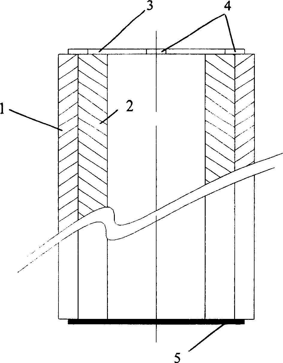
[0034] 1. Design the composite pipe and choose to manufacture the composite pipe with two-layer structure. The outer pipe 1 is a stainless steel pipe, and the inner pipe 2 is a carbon steel pipe;

[0035] 2. Analyze and calculate the interference of composite pipe and casing, and determine the casing process;

[0036] 3. Grind and pickle the surface of the selected inner tube, and at the same time, activate the outer surface of the inner tube by shot peening;

[0037] 4. Grind and pickle the surface of the selected outer tube, and at the same time, perform shot blasting activation on the inner surface of the outer tube;

[0038] 5. The preheated inner and outer tubes are preheated and fitted with slight interference to form a composite tube billet;

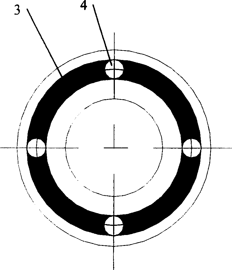
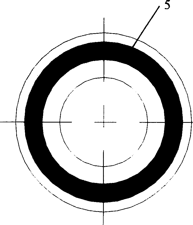
[0039] 6. Weld and seal the composite seams at both ends of the composite tube blank, one end is a fully welded sealing ring 5, the other end...


PUM


Abstract

The invention discloses a method for manufacturing a metal composite pipe. The steps include: designing the structure, performance and material selection of the composite pipe; A good single tube is formed by micro-interference fitting and end face sealing welding to form a composite tube blank, and then the rough composite tube blank is hot-rolled on the pipe rolling machine, and the rough composite tube blank is subjected to diffusion annealing, and then the finish rolling is combined, and the straightening is performed. Straightening, cutting and cutting to length, final polishing, milling, packaging and storage. The metal composite pipe manufactured by the present invention does not have any brazing material between the composite layers, and the composite interface is well realized without brazing filler metal through surface activation treatment, hot rolling and diffusion after rolling. metallurgical bonding. The invention effectively reduces the manufacturing cost of the composite pipe, can be used to produce composite pipes of various metal specifications, and can also produce special-shaped pipes such as composite square pipes and rectangular pipes, and composite rod profiles.

Description

technical field [0001] The invention relates to a method for manufacturing a metal composite pipe. Background technique [0002] The composite pipe is composed of two or more different material pipes, one material pipe is inside, and the other material pipe is outside; the pipe layers are tightly combined, and when subjected to external forces, two or more materials The pipe deforms at the same time. Composite pipes formed from different cladding materials and inner pipe materials have a wide variety of uses. Composite pipes are used in places that require corrosion resistance, prevention of cracks caused by corrosion or rust prevention, aesthetics and wear resistance. In refineries and chemical industries, composite pipes can be used for original conveying pipes, heating furnace pipes, and inspection nozzles, etc.; in water and seawater treatment, composite pipes can be used for seawater desalination production devices and hydroelectric power generation pipes, etc.; In o...

Claims


Application Information

Patent Timeline
Patent Type & Authority Patents(China)
IPC IPC(8): B32B1/08F16L9/02
Inventor 韩静涛皮华春
Owner BEIJING CHANGXING KAIDA COMPOSITE MATERIAL TECH DEV
Learn More