
Method for producing town pipe gas with liquid light hydrocarbon as material

A light hydrocarbon, liquid technology, applied in the direction of fuel, gas fuel, petroleum industry, etc., can solve the problems that are difficult to avoid international speculative capital, unstable gas production costs, and large fluctuations in price changes, and achieve supervision of technology and resource utilization Maximize and expand the use types and application scope, and the effect of good environmental protection benefits

Inactive Publication Date: 2006-02-08
GUANGZHOU GAS
View PDF0 Cites 0 Cited by
  • Summary
  • Abstract
  • Description
  • Claims
  • Application Information

AI Technical Summary

Problems solved by technology

As a clean energy source, liquefied petroleum gas has many advantages and significant environmental protection benefits, but it also has certain limitations, such as large fluctuations in price, which lead to unstable gas production costs and high prices, and the demand gap in the domestic liquefied petroleum gas market is as high as 7 million tons per year, completely dependent on imports, the risk is high, especially since there is no strategic reserve of a certain scale in China, it is difficult to avoid the risk of international speculative capital or oil monopoly capital making waves

Method used


Image

  • Method for producing town pipe gas with liquid light hydrocarbon as material
  • Method for producing town pipe gas with liquid light hydrocarbon as material
  • Method for producing town pipe gas with liquid light hydrocarbon as material

Examples


Embodiment 1

[0019] In the embodiment of the present invention, topping oil is used as raw material for mixed gas production, and gas source manufacturers in other regions can also use other liquid light hydrocarbons as raw materials according to their own conditions and production characteristics, so as to solve the problem of hydrocarbon pump startup or operation. cavitation pumping problem.

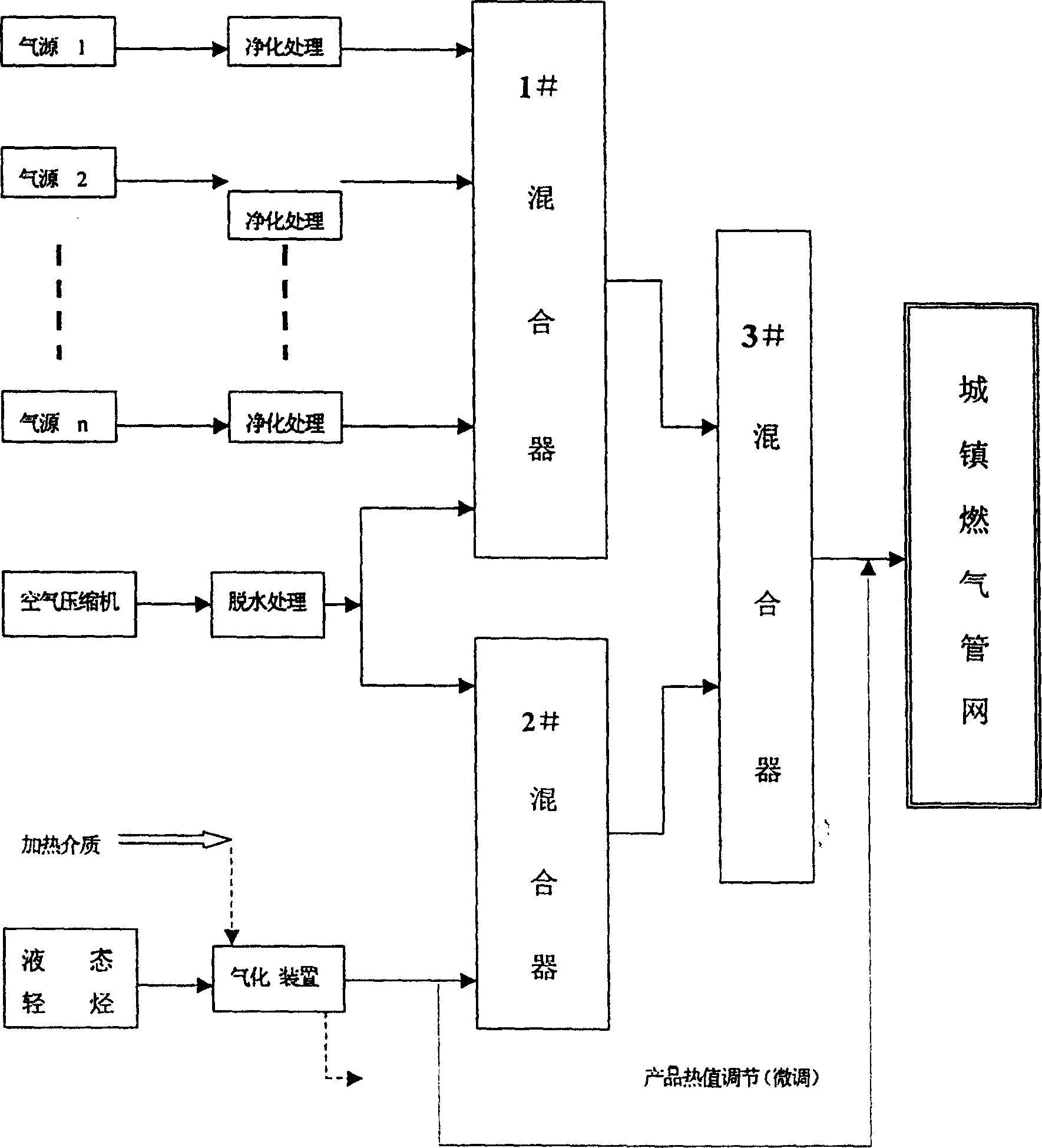
[0020] Such as figure 1 As shown, the topping oil in the raw material tank area is pressurized by the hydrocarbon pump and sent to the gasification device at a constant pressure (0.45MPa), and the excess topping oil is decompressed by the pressure control valve and then returned to the topping oil storage tank. The pressure in the raw material storage tank is related to the topping oil components and the ambient temperature. During the production process, it is generally controlled above 0.1MPa by refluxing high-temperature gas-phase topping oil or adding gas-phase LPG.

[0021] Under the action o...

Embodiment 2

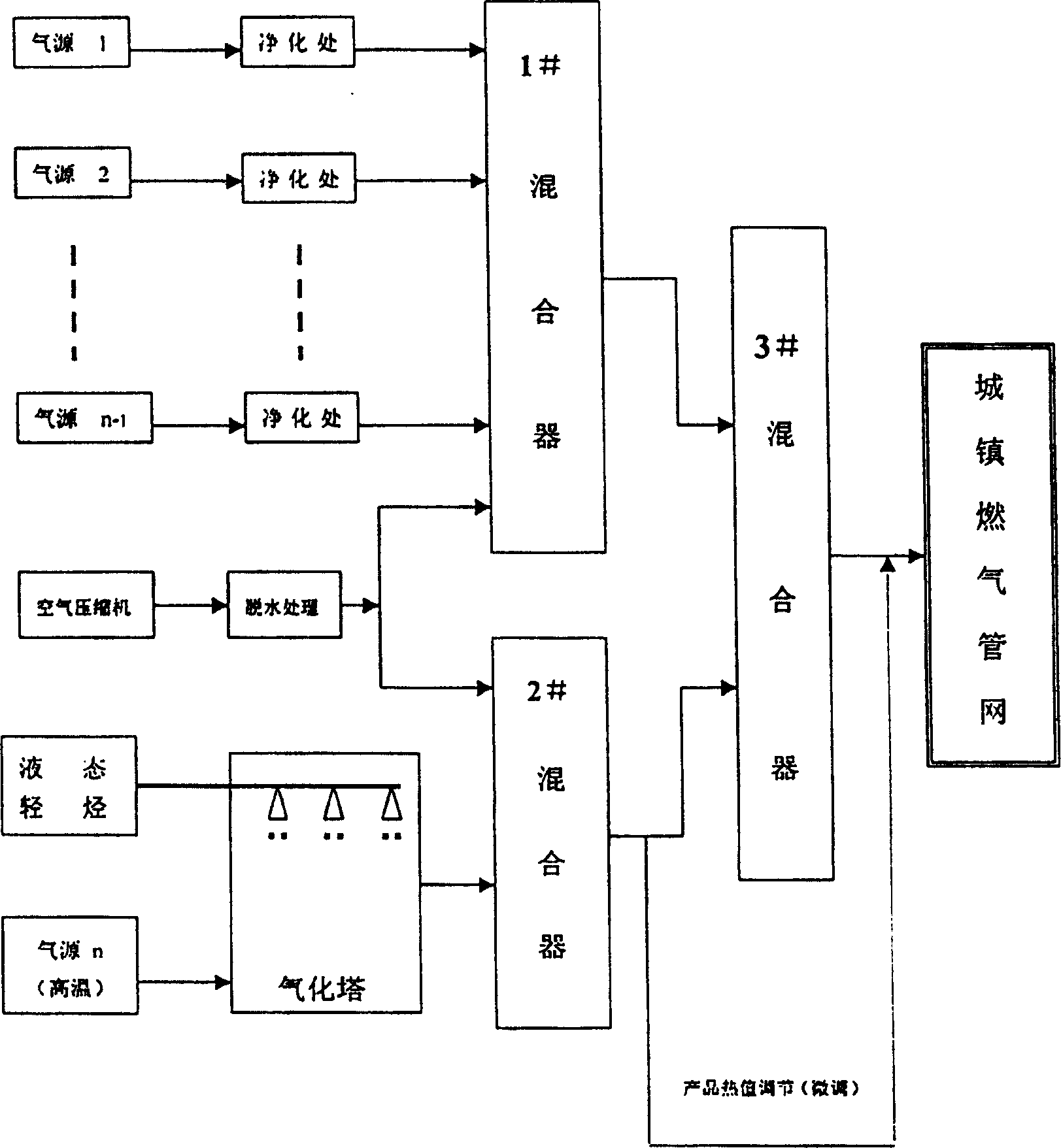
[0039] Such as figure 2 As shown, in this embodiment, mixed gas is produced by directly heating and gasifying topping oil.

[0040] The process flow of this embodiment is basically the same as that of the forced heating method. The difference is that what enters the b mixer is not pure gas phase topping oil (light hydrocarbons), but the mixture of topping oil and a certain gas source (oil-made gas). Mixed gas, liquid light hydrocarbons are vaporized by being heated by a high-temperature gas source (such as CCR reformed gas) in the gasification tower. In addition, the calorific value adjustment (fine-tuning) of the product gas is not achieved by using pure gas-phase light hydrocarbons to increase heat, but by "light hydrocarbons + certain gas source + air" mixed gas.

[0041] This embodiment makes full use of the sensible heat of the gas source n (such as CCR reformed gas), and the liquid-phase topping oil is vaporized by the sensible heat of the reformed gas after spraying i...


PUM

PropertyMeasurementUnit
boiling pointaaaaaaaaaa

Abstract

The invention discloses a process for preparing pipe-line coal gas by using liquid hydrocarbons as raw material comprising the steps of, pressurizing the hydrocarbon mixture of liquid hydrocarbons and LPG, subjecting to heating and gasification, loading vaporized hydrocarbon mixture to mixer b and mixing with a large quantity of air, purifying and disposing the air supply with combustion value and dew-point temperature lower than the gas phase lighter hydrocarbons and mixing in mixer a, charging air, further mixing gas in mixer a with gas in mixer b in mixer c.

Description

technical field [0001] The invention relates to a method for producing urban pipeline gas by using liquid light hydrocarbon as raw material. Background technique [0002] Substances composed of two elements, carbon and hydrogen, in nature are called hydrocarbons, such as oil and natural gas. Natural gas, liquefied petroleum gas, stable light hydrocarbons, gasoline, diesel, etc. derived from oil extraction and refining are also hydrocarbons. From the perspective of the entire petroleum composition, the light hydrocarbons used as fuel gas raw materials are a certain distillation range in the petroleum composition. The first section of the carbon atom arrangement is natural gas, and the number of carbon atoms is 1 or 2, called methane or ethane. The second stage is liquefied petroleum gas with carbon atoms of C3 and C4. These two sections are used for chemical raw materials and high-quality gas fuels, both of which are gaseous substances. To make it liquefied, it must be coo...

Claims


Application Information

Patent Timeline
Patent Type & Authority Patents(China)
IPC IPC(8): C10L3/00
Inventor 罗东晓
Owner GUANGZHOU GAS
Learn More