Electrochemical fluorination using interrupted current
An electrochemical, current-level technology, applied in electrolysis components, electrolysis process, halogenation electrolysis, etc., can solve problems such as current blocking, reduction in electrolytic cell conductivity, and increase in resistance
- Summary
- Abstract
- Description
- Claims
- Application Information
AI Technical Summary
Problems solved by technology
Method used
Image
Examples
Embodiment 1
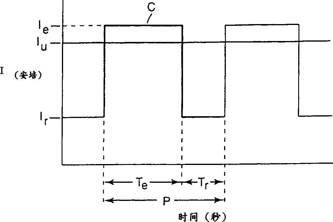
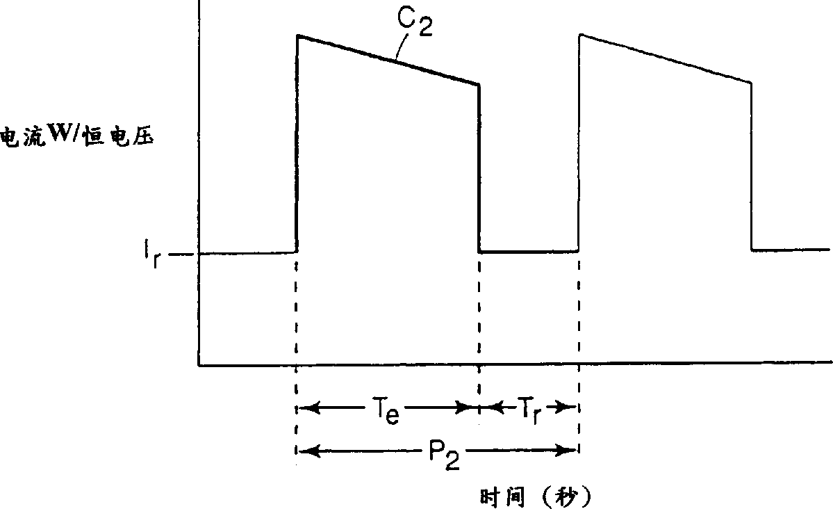
[0064] 97% by weight of anhydrous hydrogen fluoride and 3% by weight of dimethyl disulfide were charged into a 2.5-liter electrochemical fluorination cell as described in US Patent No. 2,713,593. The electrochemical fluorination cell is equipped with an overhead condenser at -40°C, a nickel anode of 0.40 square feet (3.7 square decimeter) and a single control device equipped with a cycle timer. Continue to supply a mixture of octyl sulfonyl fluoride containing 6% (weight) of dimethyl disulfide to the electrolytic cell. The operating conditions of the electrolytic cell are: pressure 30 psig, temperature 54°C, and current controlled at 53 amps / ft. 2 (5.7 Ampere / square decimeter), maintain a relatively constant voltage at 6.0V.
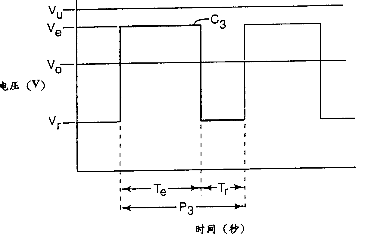
[0065] After the electrolyzer reaches a steady state, increase the current to 58A / ft 2 (6.2 amperes / square decimeter), reduce the electrolytic cell voltage to 3.3V (V r )3 seconds to make the current drop to basically 0 (T e = 27 seconds, T r = 3 seconds), s...
Embodiment 2
[0067] Basically the process used in the circulating current environment as described in Example 1 was used, maintaining the same current circulating process, without adding dimethyl disulfide, and adding octylsulfonyl fluoride. Current control at 56amps / ft 2 (6.0 ampere / square decimeter), a steady-state high voltage with a voltage of 5.6V. The low voltage is 3.3V. Perfluorooctyl sulfonyl fluoride is produced at an average yield of 21 g / 50 ampere·hour.
Embodiment 3
[0069] An electrolyte mixture containing 84% (by weight) of anhydrous hydrogen fluoride and 2.5 pounds of dimethyl disulfide is charged into an electrochemical system with a 27 square foot (251 square decimeter) anode as described in US Patent No. 2,713,593 In the fluorination electrolytic cell. Within 3 days, continue to supply a mixture of octylsulfonyl fluoride containing 94% (weight) of octylsulfonyl fluoride and 6% (weight) of dimethyl disulfide to the electrolytic cell until a stable status. The voltage under non-interrupted current is 5.8 volts. The current is 1521 amperes, and the normalized resistance is 0.028 ohm-square feet (0.26 ohm-decimeter square).
[0070] The above current is interrupted for 8 seconds every 72 seconds (T e = 72 seconds, T r = 8 seconds), so that the voltage of the electrolytic cell is lower than that of the non-intermittent electrolytic cell. This also leads to an increase in current (current density) and a decrease in normalized resistance. The v...
PUM
 Abstract
Description
Claims
Application Information
 - R&D
- Intellectual Property
- Life Sciences
- Materials
- Tech Scout
- Unparalleled Data Quality
- Higher Quality Content
- 60% Fewer Hallucinations
Browse by: Latest US Patents, China's latest patents, Technical Efficacy Thesaurus, Application Domain, Technology Topic, Popular Technical Reports.
© 2025 PatSnap. All rights reserved.Legal|Privacy policy|Modern Slavery Act Transparency Statement|Sitemap|About US| Contact US: help@patsnap.com


