Method and apparatus for generating X-ray

An optical radiation and generator technology, which is applied in the field of high-brightness X-ray or far-ultraviolet radiation methods and devices, and can solve problems such as low efficiency and low efficiency

Inactive Publication Date: 2006-08-30
伊克斯勒姆股份公司
View PDF2 Cites 3 Cited by
  • Summary
  • Abstract
  • Description
  • Claims
  • Application Information

AI Technical Summary

Problems solved by technology

However, LPP sources are limited by the relatively low efficiency of converting electron energy into laser light, and thus into X-ray radiation, necessitating the use of expensive high-power lasers

Method used


Image

  • Method and apparatus for generating X-ray
  • Method and apparatus for generating X-ray

Examples


Embodiment Construction

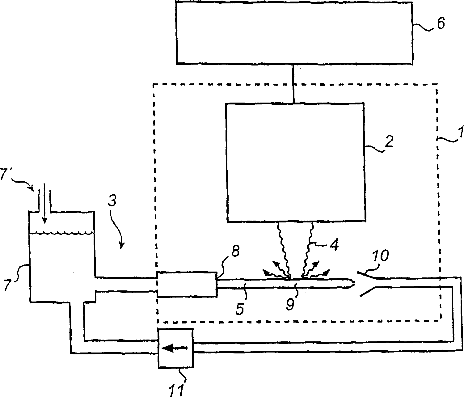
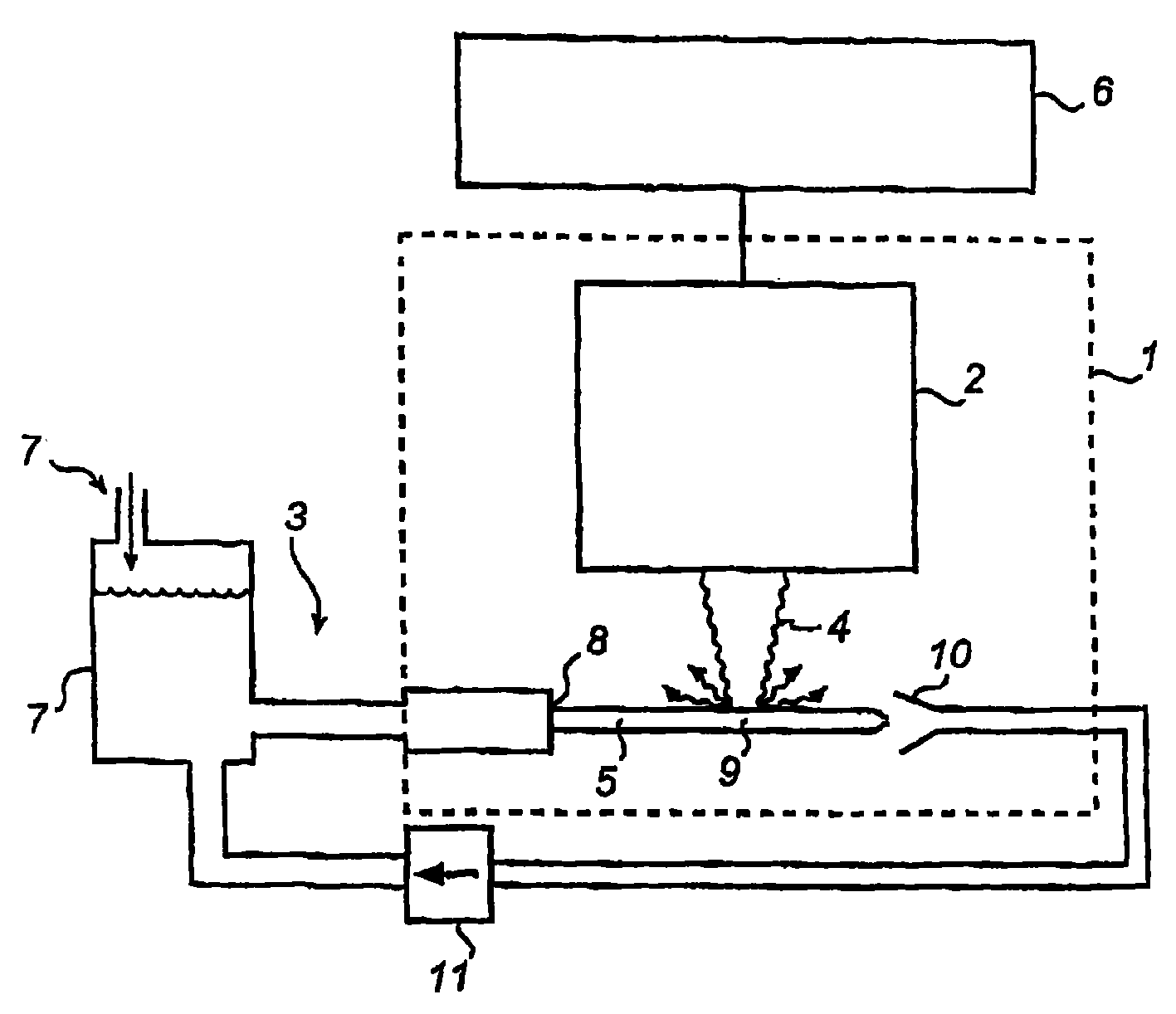
[0026] The apparatus shown in the drawings comprises a chamber 1 , an electron source 2 and a target generator 3 . The electron source 2 is arranged so that a pulsed or continuous electron beam 4 is emitted into the chamber 1 and the electron beam 4 is focused on a target 5 generated by a target generator 3 . Although not shown in the drawings, more than one electron beam 4 can be generated, these electron beams 4 being focused on the target 5 from more than one direction. Electron source 2, containing acceleration and focusing units (not shown), may be of conventional construction, powered by a voltage supply 6. The electron source 2 can be anything from a simple cathode source to a complex high energy source such as a racetrack, depending on the desired characteristics of the electron beam 4 .

[0027] As will be described below, X-ray or EUV radiation (indicated by the arrow in the figure) is produced by the interaction of the electron beam 4 with the target 5 in the chamb...


PUM


Abstract

In a method and an apparatus for generating X-ray or EUV radiation, an electron beam is brought to interact with a propagating target jet, typically in a vacuum chamber. The target jet is formed by urging a liquid substance under pressure through an outlet opening. Hard X-ray radiation may be generated by converting the electron-beam energy to Bremsstrahlung and characteristic line emission, essentially without heating the jet to a plasma-forming temperature. Soft X-ray or EUV radiation may be generated by the electron beam heating the jet to a plasma-forming temperature.

Description

technical field [0001] The present invention relates generally to a method and apparatus for producing X-rays or extreme ultraviolet (EUV) radiation, and more particularly to high intensity X-rays or extreme ultraviolet (EUV) radiation. The radiation produced can be used, for example, in medical diagnostics, non-destructive testing, lithography, microscopy, materials science, or some other X-ray or EUV application. Background technique [0002] X-ray sources with high power and brightness are used in many fields, such as medical diagnosis, non-destructive testing, crystal structure analysis, surface physics, lithography, X-ray fluorescence and microscopy. [0003] In some applications, X-rays are used to image the interior of objects that are opaque to visible light. For example, in medical diagnosis and material inspection, X-ray radiation of 10-1000keV is used, that is, hard X-ray radiation . Conventional hard X-ray sources, in which an electron beam is accelerated to a ...

Claims


Application Information

Patent Timeline
Patent Type & Authority Patents(China)
IPC IPC(8): H05G2/00G21K5/00G03F7/20G21K5/02G21K5/08G21K7/00H01J35/08H01L21/027
CPCH01J2235/082H05G2/005H05G2/003H01J35/08H01J35/112
Inventor 汉斯·赫茨奥斯卡·亨伯格
Owner 伊克斯勒姆股份公司
Why Eureka
Try Eureka