Molding method and molding mechanism for a biologic material of fabricable material
A technology for biomass materials and molding materials, which is used in material molding presses, biofuels, waste fuels, etc., can solve the problems of high energy consumption, easy crushing, and high brittleness, and achieve energy saving, good plasticity and durability. moist effect
- Summary
- Abstract
- Description
- Claims
- Application Information
AI Technical Summary
Problems solved by technology
Method used
Image
Examples
Embodiment 1
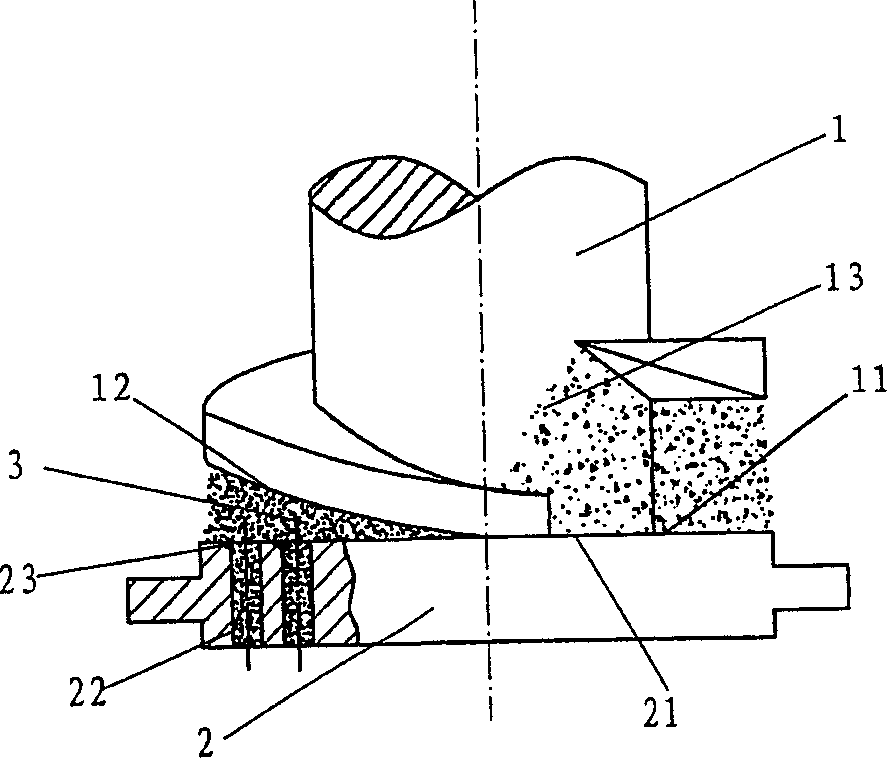
[0059]The method of this embodiment is applicable to the shaping and processing of biomass combustion materials. Before the shaping and processing of the method of the present invention, the biomass material to enter into the shaping state should be loose. Therefore, when necessary, the raw materials that are not in loose shape should be , such as crop stalks, shrubs, etc., should be crushed and processed into loose form. However, for raw materials that are in a loose state, such as sawdust, similar to solid waste generated by wood processing, it can be determined whether crushing is required depending on the particle size of the raw materials.
[0060] In this embodiment, the loose biomass material can be directly input into the wedge-shaped extrusion cavity, and directly carry out extrusion molding process therein. In the present invention, at least one wedge-shaped extrusion cavity is formed between the extrusion head and the extrusion surface of the forming die. Specifical...
Embodiment 2
[0068] The molding method, molding principle, and molding mechanism of this embodiment are the same as those of Embodiment 1, and will not be repeated here.
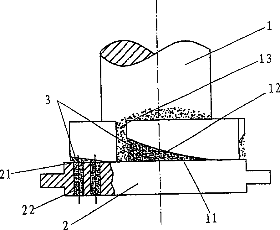
[0069] like figure 2 , image 3 As shown, the difference between this embodiment and Embodiment 1 is that the end face 11 of the extrusion head 1 is provided with more than two arc-shaped slopes 12, and the arc-shaped slopes 12 are compatible with the planar molding die 2. The extrusion surface 21 is formed with more than two wedge-shaped extrusion cavities 3, and the two or more wedge-shaped extrusion cavities 3 are first connected from the large end to the small end.
[0070] The motion mode of this embodiment can adopt the same motion mode as that of Embodiment 1. That is, the extrusion head 1 can be driven by a power to rotate along its vertical axis, and the direction of rotation is the same direction from the small end to the large end of the extrusion chamber 3, so that the biomass in the extrusion chamber 3 T...
Embodiment 3
[0072] The forming method, forming principle and forming mechanism of this embodiment are the same as those of Embodiment 1 and Embodiment 2, and will not be repeated here.
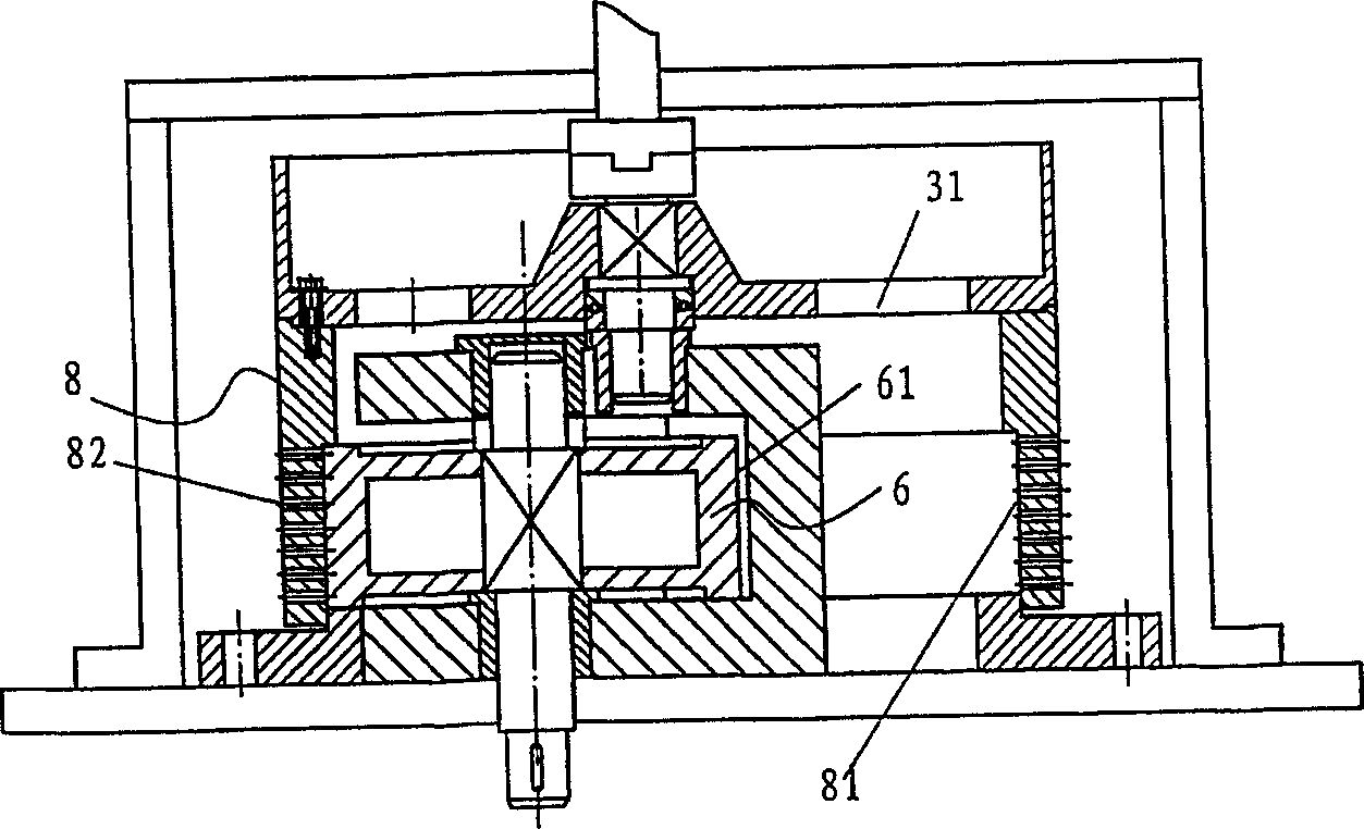
[0073] like Figure 4 As shown, the difference from the above-mentioned embodiments is that the movement of the extrusion head 1 relative to the molding die of this embodiment is different from that of the first and second embodiments. That is to say, the molding die 2 can be driven by a power to rotate along its vertical axis, and the direction of rotation is the opposite direction from the small end to the large end of the extrusion chamber 3, so that the biomass material in the extrusion chamber 3 It has a tendency to move toward the small end of the extrusion cavity 3 . The extrusion head 1 can be in a static design, so that the molding die 2 can press the surface 21 with respect to the end surface 11 with a slope surface to generate relative sliding movement between planes. Thereby constituting the...
PUM
| Property | Measurement | Unit |
|---|---|---|
| particle size | aaaaa | aaaaa |
| particle size | aaaaa | aaaaa |
Abstract
Description
Claims
Application Information
 - R&D
- Intellectual Property
- Life Sciences
- Materials
- Tech Scout
- Unparalleled Data Quality
- Higher Quality Content
- 60% Fewer Hallucinations
Browse by: Latest US Patents, China's latest patents, Technical Efficacy Thesaurus, Application Domain, Technology Topic, Popular Technical Reports.
© 2025 PatSnap. All rights reserved.Legal|Privacy policy|Modern Slavery Act Transparency Statement|Sitemap|About US| Contact US: help@patsnap.com


