
Optical fiber microelectronic pressure sensor for mechanical system and multiplexing structure thereof

A micro-electro-mechanical and system pressure technology, applied in the direction of force measurement by measuring the change of optical properties of materials when they are stressed, can solve the problems of the sensitivity of sensor output and the inability to achieve distributed pressure measurement, to avoid residual pressure. Stress instability, high speed, and simple detection of the effect of the optical path

Inactive Publication Date: 2006-11-08
NANJING NORMAL UNIVERSITY
View PDF0 Cites 0 Cited by
  • Summary
  • Abstract
  • Description
  • Claims
  • Application Information

AI Technical Summary

Problems solved by technology

[0008] The above example uses LED as the light source, and the LED light source will drift with the temperature change, so the sensitivity of the sensor output will be affected
Moreover, this cavity length demodulation method is difficult to combine with multiplexing technology to form a distributed measurement network. It can only measure single-point pressure and cannot realize distributed pressure measurement.

Method used


Image

  • Optical fiber microelectronic pressure sensor for mechanical system and multiplexing structure thereof
  • Optical fiber microelectronic pressure sensor for mechanical system and multiplexing structure thereof
  • Optical fiber microelectronic pressure sensor for mechanical system and multiplexing structure thereof

Examples


Embodiment Construction

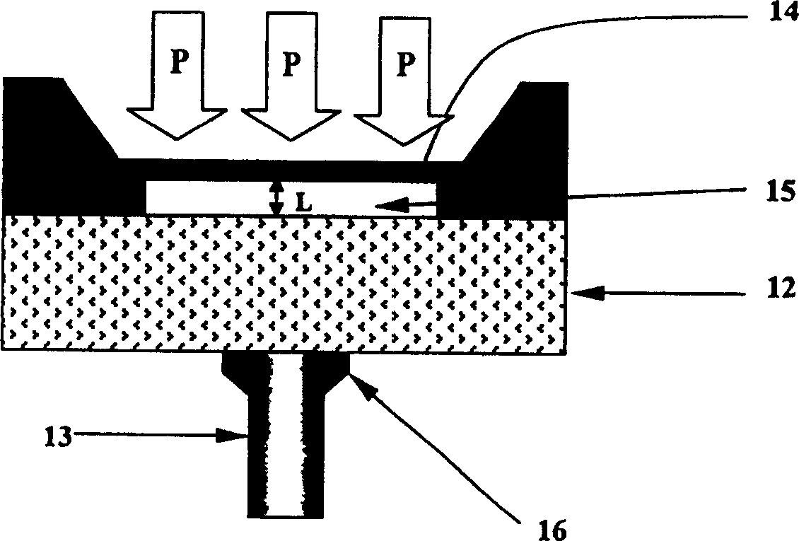
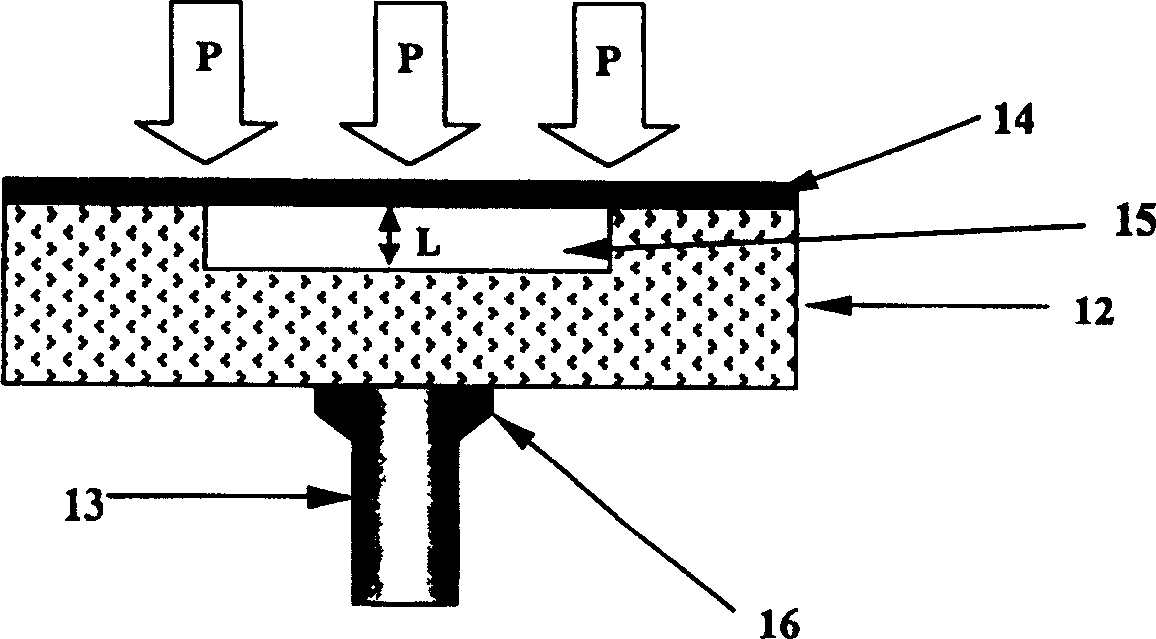
[0041] Since the borosilicate glass 12 and the single crystal silicon film 14 are bonded together by a vacuum anodic bonding process, the internal air pressure of the Fabry-Perot chamber is approximately equal to the ambient air pressure in the vacuum anodic bonding chamber, so it can be used as an absolute Reference pressure for the pressure sensor.

[0042] The light of wavelength λ is coupled into the Fabry-Perot cavity through the optical fiber, and the light is reflected back and forth on the upper surface of the borosilicate glass and the lower surface of the single crystal silicon film to form multi-beam interference. When the single crystal silicon film 14 is under pressure, it will Bending occurs so that the cavity length L of the Fabry-Perot cavity becomes L′. According to the multi-beam interference principle of the Fabry-Perot cavity, for light with a wavelength of λ, the interference light intensity will change, resulting in a wavelength The reflectivity of λ ligh...


PUM

PropertyMeasurementUnit
diameteraaaaaaaaaa
thicknessaaaaaaaaaa

Abstract

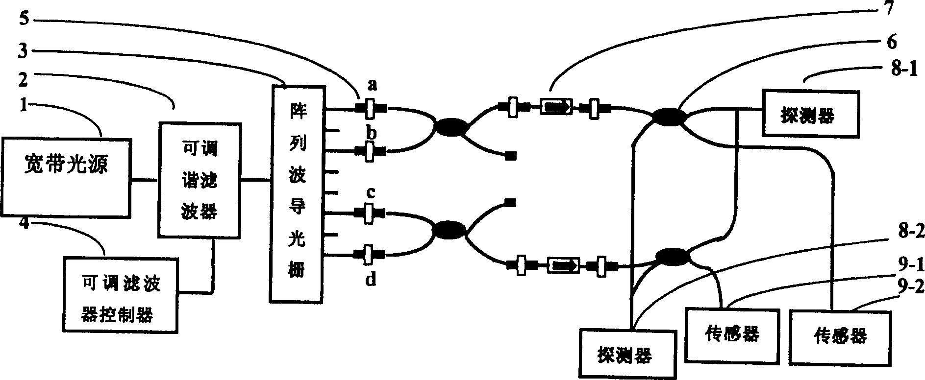
The optical fiber MEMS pressure sensor and its multiplexing device are mainly used for the measurement of absolute and relative pressure. The polished end face of the optical fiber (13) with the end face polished in the sensor is connected with the borosilicate glass substrate (12), and the connected The outer end of the surface is connected by photocuring epoxy resin (16); on the borosilicate glass substrate is a monocrystalline silicon film (14), and a single crystal silicon film (14) is arranged between the lower part of the center of the monocrystalline silicon film and the borosilicate glass substrate. The cavity is: Fabry-Perot cavity (15). Its multiplexing structure broadband light source (1) and tunable filter controller (4) are connected with the control tunable filter (2), and the output end of the tunable filter is connected with the arrayed waveguide grating (3), and the arrayed waveguide The output end of the grating is respectively connected to the photodetector and the sensor through the optical fiber adapter (5), the optical one-way isolator (7), and the optical fiber coupler (6), and the change of the cavity length of the Fabry-Perot cavity of the sensor is detected Measure the pressure on the single crystal silicon membrane.

Description

technical field [0001] The invention relates to a sensor multiplexing system for measuring pressure, which is mainly used for the measurement of absolute and relative pressure, and especially uses the dual-wavelength cavity length demodulation principle and multiplexing technology to measure multi-point pressure to realize distributed pressure measurement. Background technique [0002] With the continuous development of microelectronics technology and silicon-based microsensors, pressure sensors have rapidly developed towards miniaturization, high performance and suitable for mass production. The continuous development of optical fiber sensing technology makes the organic combination of optical multiplexing technology and optical fiber sensing technology, and realizes the distributed measurement of physical quantities. [0003] image 3 It is a brief structural illustration of the fiber optic MEMS pressure sensor commonly used at present. Published...

Claims


Application Information

Patent Timeline
Patent Type & Authority Patents(China)
IPC IPC(8): G01L1/24
Inventor 王鸣李明王婷婷聂守平
Owner NANJING NORMAL UNIVERSITY
Learn More