Ion removal from water using activated carbon electrodes
A technology of activated carbon and deionization, which is applied in the direction of ion exchange, ion exchange regeneration, ion exchange treatment devices, etc., and can solve the problems of long-term durability and unreliability
- Summary
- Abstract
- Description
- Claims
- Application Information
AI Technical Summary
Problems solved by technology
Method used
Image

Examples
Embodiment 1
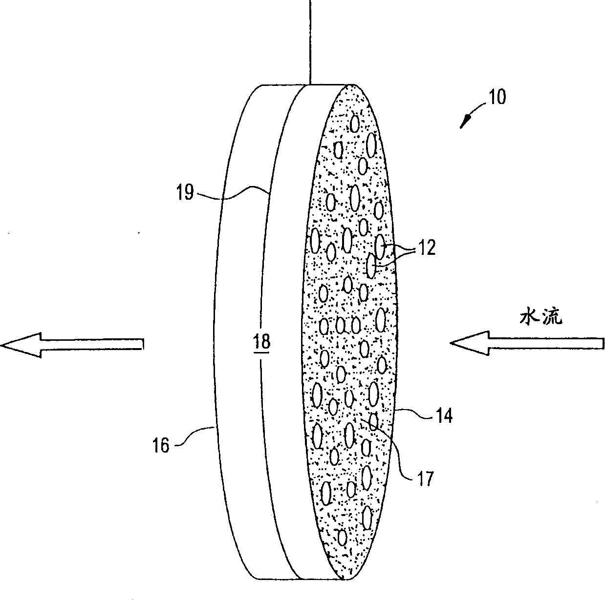
[0079] A mixture of 55.6% phenolic resin, 22.2% cellulose fibers, 14.7% cordierite powder, methylcellulose, 0.9% sodium stearate, and 2% phosphoric acid was extruded to produce 600 units / square inch of carbon honeycomb body. The honeycomb was then cured at about 150°C, carbonized and activated at about 900°C (under nitrogen and carbon dioxide, respectively). The honeycomb was then cut to a size of 55 x 20 x 4.8 mm. A copper wire is inserted into a cell of the honeycomb and its ends are welded to the honeycomb to mechanically connect the copper wire to the honeycomb. This honeycomb was connected to another identical honeycomb using polypropylene monofilaments about 1 mm thick. The monofilaments are wound around the connected ends of the two honeycombs so that the honeycombs are joined but the two electrodes remain separated. The assembly was placed in water containing about 900 ppm sodium chloride. A potential difference of about 1.2 volts was then applied across the electr...
Embodiment 2
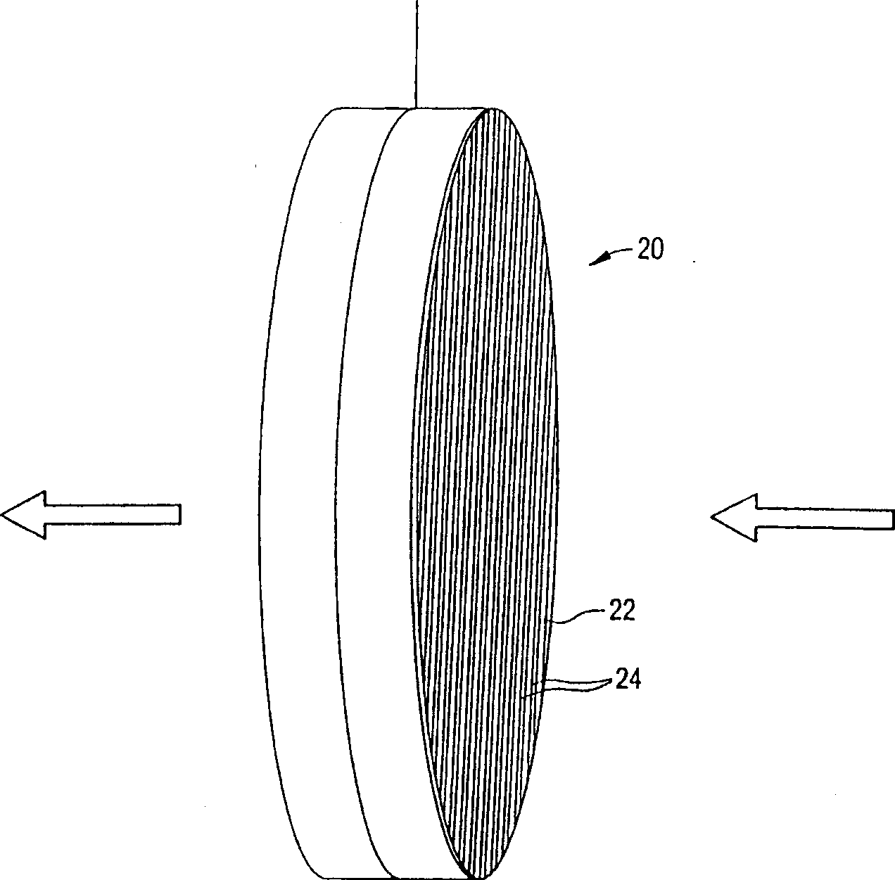
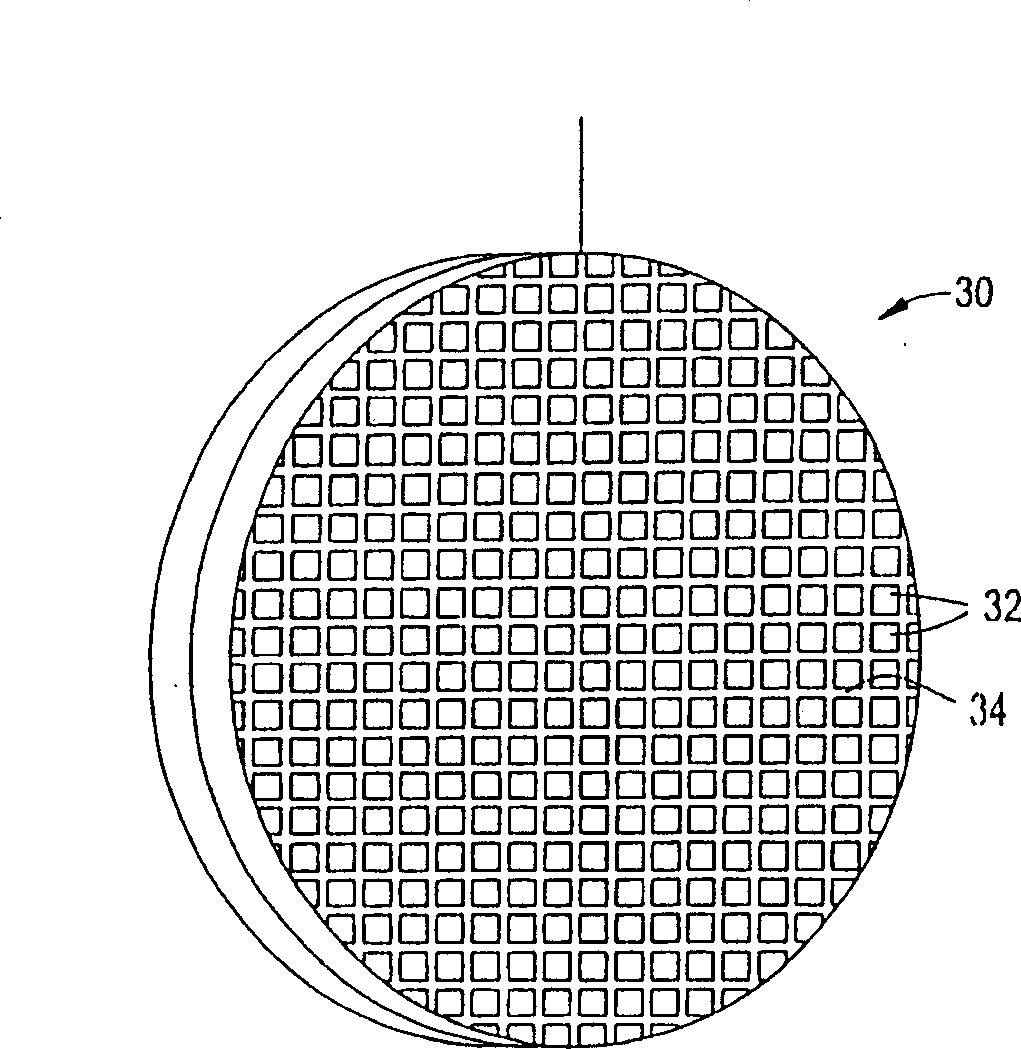
[0081] Mix and grind the phenolic resin with various fillers given in Example 1 (such as cellulose fiber, ceramic particle filler, phosphoric acid and methylcellulose) to prepare an activated carbon honeycomb body. The mixture was extruded through a 400 units per square inch die, dried at 80-90°C, and cured at about 150°C in circulating air. The cured honeycomb was then carbonized at about 900°C in nitrogen and activated in carbon dioxide to obtain activated carbons with different surface areas. The surface area of activated carbon is controlled by controlling the activation temperature between 1-12 hours. The longer the time at this temperature, the higher the resulting surface area. During carbonization, the honeycomb shrinks and the cell density increases to about 600 cells / in2. The honeycomb body is then cut to a suitable thickness to produce electrodes.
[0082] The two electrodes were placed in a plastic container serving as a housing, and the size of the container ...
Embodiment 3
[0085] To understand the effect of carbon structure on performance, electrodes were processed under different activation times and temperatures to obtain electrodes with surface areas ranging from approximately 500 m2 / g to 1769 m2 / g (based on carbon weight). The sodium chloride solution was then passed through these electrodes as described above. Figure 8 Data normalized to carbon in the counter electrode is shown. As shown, the removal rate and capacity increase with increasing surface area, and after a certain point, the removal rate and capacity decrease. The Y-axis of the graph is the removal of sodium chloride normalized to the grams of carbon in the electrode. The reasons for the unexpectedly lower performance at higher surface areas are explained below. Figure 9The effect of salt concentration on removal performance is shown for the removal of sodium chloride using an electrode with a surface area of 1039 square meters. These results were again normalized to the ...
PUM
 Abstract
Description
Claims
Application Information
 - R&D
- Intellectual Property
- Life Sciences
- Materials
- Tech Scout
- Unparalleled Data Quality
- Higher Quality Content
- 60% Fewer Hallucinations
Browse by: Latest US Patents, China's latest patents, Technical Efficacy Thesaurus, Application Domain, Technology Topic, Popular Technical Reports.
© 2025 PatSnap. All rights reserved.Legal|Privacy policy|Modern Slavery Act Transparency Statement|Sitemap|About US| Contact US: help@patsnap.com