
Optical fiber laser with multi-wavelength output

A technology for outputting optical fibers and lasers, applied to lasers, laser components, phonon exciters, etc., can solve problems such as unstable performance, limited transmission rate, complex structure, etc., to improve stability, reduce size, and expand application range Effect

Inactive Publication Date: 2003-03-19
HUAWEI TECH CO LTD
View PDF0 Cites 17 Cited by
  • Summary
  • Abstract
  • Description
  • Claims
  • Application Information

AI Technical Summary

Problems solved by technology

However, there is no relatively mature multi-channel multi-wavelength output structure at present. The common method is to make single-wavelength (DBR—Distributed Bragg Reflector) lasers or fiber lasers into arrays and package them together, which has complex structures and unstable performance. , and each wavelength requires a separate driving voltage or temperature control, etc.
Recently, tunable lasers based on mode locking have received a lot of attention, but this method has special limitations on the transmission rate. In recent years, Arrayed Waveguide Grating (AWG—Arrayed Waveguide Grating) technology has developed rapidly. Its performance, The price has reached the level of commercialization, arrayed waveguide grating AWG can be used as an integrated optical filter array, but the application of arrayed waveguide grating AWG to fiber laser has not yet been found

Method used


Image

  • Optical fiber laser with multi-wavelength output
  • Optical fiber laser with multi-wavelength output
  • Optical fiber laser with multi-wavelength output

Examples


Embodiment 1

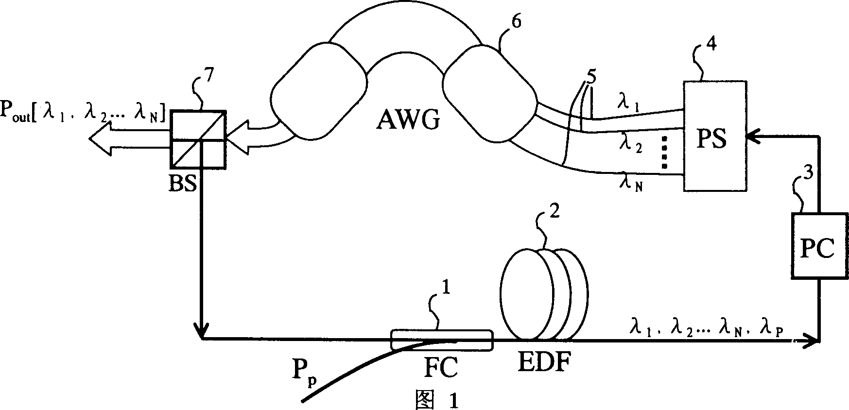
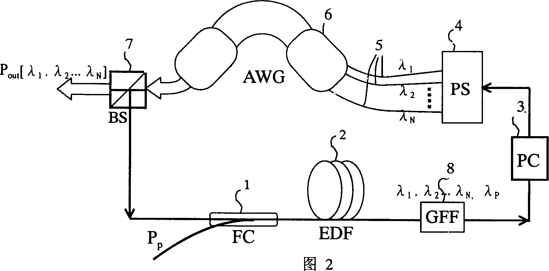
[0026] Figure 1~ image 3 As shown, this embodiment includes:

[0027] A pumping source is used to provide pumping light Pp for the optical coupler 1. The pumping source is not shown in the illustration, and only the illustration of the pumping light Pp is given as the input pumping light Pp;

[0028] An optical coupler (FC——Fiber Coupler) 1 is coupled between the pump source and the fiber amplifier 2, and is used to transmit the pump light and the optical input signal of the pump source to the fiber amplifier 2;

[0029] A fiber amplifier 2, excited by the pumping light of the pump source, is used to generate spontaneous emission light of various wavelengths and directions. In this implementation, the fiber amplifier 2 is an erbium-doped fiber (EDF—Erbium Doped Fiber) amplifier, That is, the erbium-doped fiber EDF is used as the gain medium;

[0030] A polarization controller (PC——Polarization Controller) 3 is connected behind the fiber amplifier 2, and is used to adjust the...

Embodiment 2

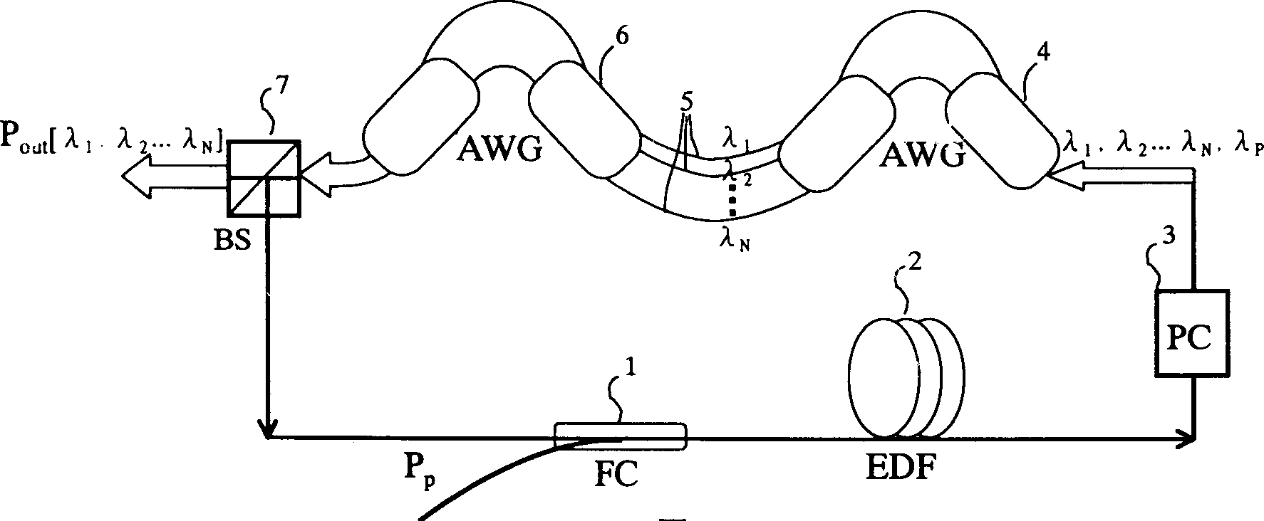
[0035] Embodiment 2: as Figure 4 As shown, the difference between this embodiment and Embodiment 1 lies in the output mode of the light source. In this embodiment, light of different wavelengths is output through different channels. This embodiment includes:

[0036]A pumping source is used to provide the pumping light Pp for the optical coupler 1, and the pumping source is not shown in the figure, and only the illustration of the pumping light Pp is given as the input pumping light Pp;

[0037] An optical coupler (FC——Fiber Coupler) 1 is coupled between the pump source and the fiber amplifier 2, and is used to transmit the pump light and the optical input signal of the pump source to the fiber amplifier 2;

[0038] A fiber amplifier 2, which is excited by the pumping light of the pump source, is used to generate spontaneous emission light of various wavelengths and directions; in this implementation, the fiber amplifier 2 also selects an erbium-doped fiber (EDF——Eribum Doped...


PUM


Abstract

The optical fiber laser with multiband output includes pump source, light coupler, polarization controller, light splitter, array waveguide grating and light beam splitter connected successively to constitute loop. The present invention realizes the multiband amplification with single pump source by connecting AWG into fiber loop with doped fiber, using the AWG as intracavity light filler to select resonant wavelength and amplify radiation, and coupling the AWG multiplexing end to doped fiber. The device of the present invention has simple and small integrated structure, various light source with different wavelength and wavelength interval may be realized via altering AWG structure parameters, and standard wavelength and wavelength interval of C-band and L-band in ITU-T may be realized reliably.

Description

technical field [0001] The invention relates to a fiber optic light source, in particular to a fiber optic light source with multi-wavelength output, suitable for using amplified spontaneous emission (ASE) light as an auxiliary pump source. Background technique [0002] Broadband light sources have been studied continuously due to their many applications such as extension to gyroscopic sensors, light sources for testing optical components, and modulated spectra for general access networks. In particular, light sources utilizing ASE light from optical fibers doped with rare earth metals (such as erbium) are relatively good broadband light sources because they exhibit characteristics of wide band, high power, and low loss. For this erbium-doped optical fiber ( All research efforts made by EDF) broadband light sources are about the single band from 1520 to 1560 nanometers, that is, the C-band (C-Band). Most of the existing optical communication components and the traditional er...

Claims


Application Information

Patent Timeline
IPC IPC(8): H01S3/00H01S3/067
Inventor 刘玥李长春
Owner HUAWEI TECH CO LTD
Learn More