Micro-piezoelectric driver for MEMS

A micro-piezoelectric and driver technology, applied in the direction of piezoelectric devices/electrostrictive devices, piezoelectric/electrostrictive/magnetostrictive devices, microstructure devices composed of deformable elements, etc., can solve the driving displacement And problems such as limited deflection, increased driving voltage, and large driver size, etc., to achieve good device driving performance, lower driving voltage, and high device reliability.

Inactive Publication Date: 2004-03-24
TSINGHUA UNIV
View PDF0 Cites 12 Cited by
  • Summary
  • Abstract
  • Description
  • Claims
  • Application Information

AI Technical Summary

Problems solved by technology

Most of the existing micro-execution structures using these principles have a large driver size and occupy a large chip area, but the realized driving displacement and deflection are limited, the manufacturing process is complicated, the reliability is not high, the power consumption is large, and the life is short
Most of the MEMS piezoelectric film drive methods that have been widely studied use a cantilever beam structure. Due to the limited elongation of the piezoelectric film, the maximum deflection displacement on the cantilever beam structure is very limited. This characteristic limits the piezoelectric drive method. The wide application in the field of MEMS has resulted in the emergence of very few mature MEMS commercial devices driven by piezoelectric films.
To achieve large vertical displacement or deflection of this kind of cantilever driving structure, it is required to lengthen the length of the beam and increase the driving voltage, which increases the static deflection of the cantilever beam caused by gravity on the one hand, so that when no voltage is applied, the cantilever will have Large deflection displacement, which seriously limits its application range
On the other han

Method used


Image

  • Micro-piezoelectric driver for MEMS
  • Micro-piezoelectric driver for MEMS
  • Micro-piezoelectric driver for MEMS

Examples


Embodiment Construction

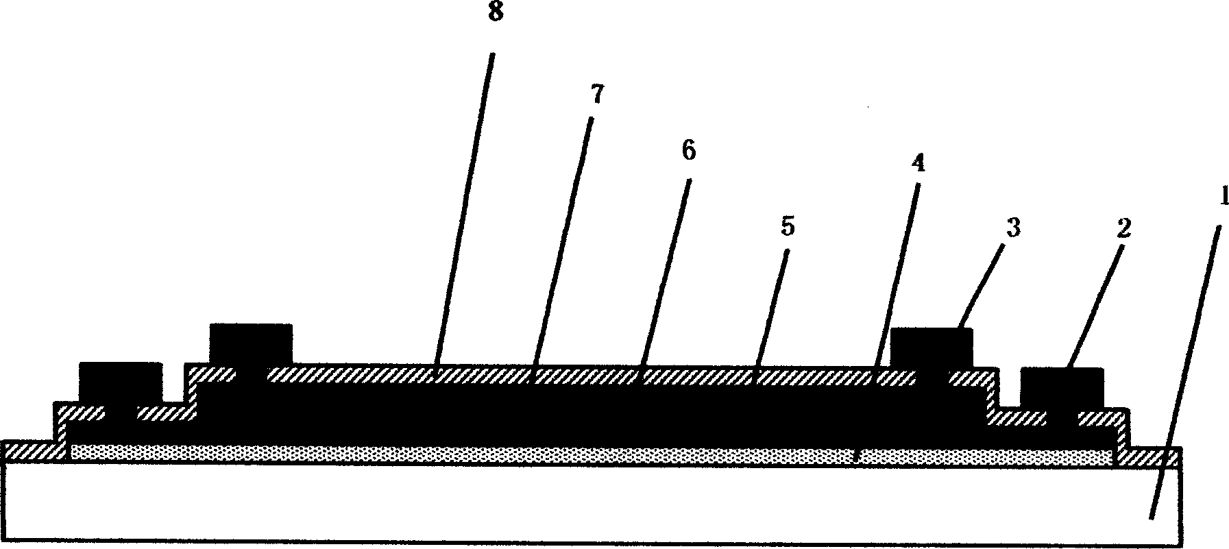
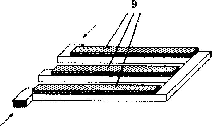
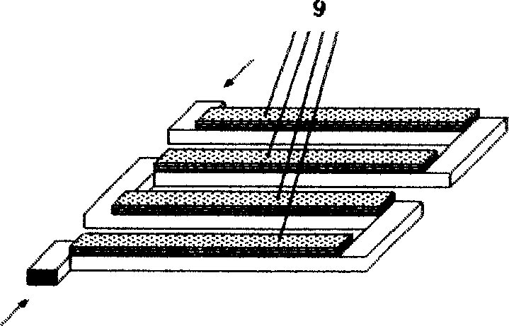
[0016] The invention is a micro piezoelectric driver for MEMS. The micro-piezoelectric driver adopts a folded multi-stage piezoelectric composite multi-layer elastic suspended film structure, that is, a continuous folded parallel arm 9 is formed on the substrate silicon chip 1, and each arm 9 is formed from the elastic silicon substrate layer 1. Covered with a buffer layer 4 from bottom to top, a lower film electrode layer 5 that is not connected to each other, a piezoelectric film 6 with a certain shape, and an upper film electrode layer 7 are compositely stacked, and an insulating dielectric layer 8 can also be covered on the upper electrode film. 7 surfaces; the lower film electrode layer 5 is connected with the lower electrode lead 2, and the upper film electrode layer 7 is connected with the upper electrode lead 3 (as figure 1 shown); on each folded arm, a driving arm using piezoelectric effect is formed, and one or both sides of the driving structure are connected to the...


PUM


Abstract

The miniature piezoelectric driver capable of producing deflection angle and vertical displacement for MEMS is characterized by that its structure is a kind of suspension folded piezoelectric composite multi-layer film elastic driving arm, it has at least two sections or more than two sections of parallel driving arms. The driving arms of two sides of suspension structure are connected with substrate. Every driving arm contains elastic layer and piezoelectric composite film on the elastic layer. When the driving voltages with opposite polarity are applied on the upper and lower electrodes of piezoelectric films on the adjacent parallel different driving arms, the parallel adjacent piezoelectric driving arms can produce opposite bend, and on the driving arm of middle portion positioned in the suspension structure the maximum vertical displacement or deflection angle can be produced.

Description

technical field [0001] The invention belongs to the field of micro-electronic machinery, in particular to a micro piezoelectric driver for MEMS. Background technique [0002] Micro Electro Mechanical System (MicroElectroMachanical System), referred to as MEMS. It is the cutting-edge science in high-tech fields such as miniaturization, integration, intelligence, informatization, and advanced manufacturing. MEMS is based on advanced semiconductor technology and integrated circuit manufacturing technology, which broadens the method of manufacturing complex electromechanical systems on microchips. These methods combine the large-scale integrated circuit manufacturing technology and the unique special process of micromachining technology, and integrate micromechanical structures, microactuators, microelectronic devices and circuit systems to form a so-called system on chip (SOC). The entire MEMS involves many disciplines from design to manufacture, as well as computer technolog...

Claims


Application Information

Patent Timeline
IPC IPC(8): B81B3/00H01L41/08
Inventor 方华军刘理天
Owner TSINGHUA UNIV
Why Eureka
Try Eureka