Dispersion compensating transmission optical fiber matched with orthochromatic dispersion and ortho chromatic dispersion slope unimodel optical fiber and use

A transmission optical fiber and dispersion compensation technology, applied in the transmission system, electromagnetic wave transmission system, optics, etc., can solve the problems of large proportion, small effective area, unfavorable transmission, etc.

Active Publication Date: 2004-07-21
SICHUAN LEFEI OPTOELECTRONICS TECH CO LTD +1
View PDF5 Cites 15 Cited by
  • Summary
  • Abstract
  • Description
  • Claims
  • Application Information

AI Technical Summary

Problems solved by technology

At present, the most widely used method is to add a module composed of dispersion compensating fiber (DCF) to the fiber link. For DCF, in order to obtain a large negative dispersion, the refractive index of the fiber core is high and the geometry The size should be small, so that in the core of the DCF, the amount of germanium doped is relatively large, so that the attenuation, PMD and nonlinear effects of the DCF will be relatively poor
In addition, another disadvantage of using the DCF method is that DCF increases the system attenuation, system cost, PMD and nonlinear effects, but does not increase the length of the system
[0003] Patent CN1351267A/US 2002/0076186A1 discloses a fiber with positive dispersion for in-line compensation of dispersion, but its negative dispersion at 1550nm is only -12ps/(nm.km) to -4ps/(nm .km), it is impossible to fully compensa

Method used


Image

  • Dispersion compensating transmission optical fiber matched with orthochromatic dispersion and ortho chromatic dispersion slope unimodel optical fiber and use
  • Dispersion compensating transmission optical fiber matched with orthochromatic dispersion and ortho chromatic dispersion slope unimodel optical fiber and use
  • Dispersion compensating transmission optical fiber matched with orthochromatic dispersion and ortho chromatic dispersion slope unimodel optical fiber and use

Examples


Embodiment 1-2

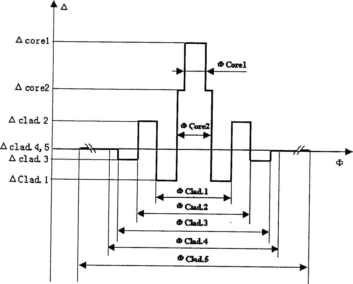
[0074] Table 3 lists the figure 1 Table 5 shows the main properties of the obtained optical fiber.

[0075] ΔCore1

Embodiment 3-4

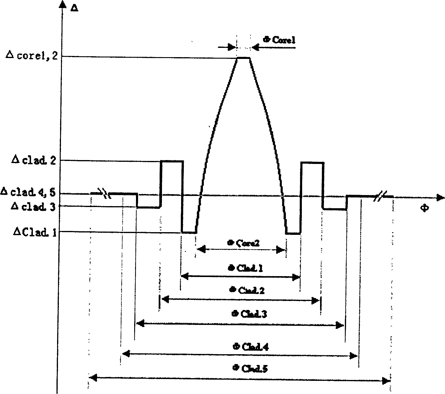
[0077] Table 4 lists the figure 2 Table 5 shows the results of the obtained optical fiber for the second group of refractive index distributions.

[0078] ΔCore1

[0079] The main optical parameters of above-mentioned 4 embodiments are as shown in table 5, and its dispersion characteristic is as follows Figure 7 shown.

[0080] Optical parameters at 1550nm

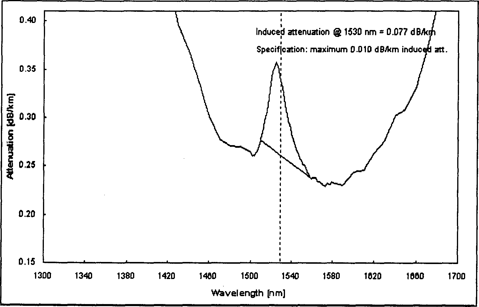
[0081] For the optical fibers of the above embodiments, by adjusting the doping to ensure that the viscosity is matched, the hydrogen loss of the measured optical fibers is less than 0.01dB / km. By analyzing the composition of the section of the optical fiber, combined with the measurement of the section refractive index and the calculation of formula (1), the viscosity distribution trend on the section of the optical fiber is as follows Figure 9 shown.


PUM

PropertyMeasurementUnit
Dispersionaaaaaaaaaa

Abstract

The waveguide structure of single-mode optical fibre comprises layered fibre core and layered clad. The fibre core is set with two core layers in different refractive indexed and layered clad consists of five layered clads. The codeposition of fluorine and germanium is applied by utilizing PCVD process to replace independent deposition of fluorine or germanium in deposition process for fibre core and clad so optical, mechanical and environmental performance of optical fibre is very much improved. The single-mode optical fibre produced in the present invention can be used in transmission of DWDM system.

Description

technical field [0001] The present invention relates to a class of negative dispersion single-mode optical waveguide fiber designed for large-capacity and high-speed transmission systems and the use of the fiber. Specifically, the involved single-mode fiber has certain negative dispersion and negative dispersion slope at 1450-1675nm , with low attenuation, low polarization mode dispersion (PMD), large effective area, low splice loss, excellent bending resistance and environmental characteristics. Background technique [0002] Since the mid-1990s, with the development of erbium-doped fiber amplifiers and wavelength division multiplexing technology, optical fiber communication has entered an unprecedented high-speed development stage. With the development of wavelength division multiplexing, it is found that nonlinear effects between wavelengths, such as four-wave mixing, self-phase modulation, cross-phase modulation, etc., limit the expansion of system...

Claims


Application Information

Patent Timeline
IPC IPC(8): H04J14/02
Inventor 韩庆荣张树强罗杰
Owner SICHUAN LEFEI OPTOELECTRONICS TECH CO LTD
Why Eureka
Try Eureka