Current sensor

A technology of current sensor and resistance, applied in the direction of voltage/current isolation, measuring current/voltage, instruments, etc., to achieve the effect of enhancing stability, improving saturation characteristics, linearity, and frequency bandwidth

Inactive Publication Date: 2004-11-17
HUAZHONG UNIV OF SCI & TECH
View PDF0 Cites 46 Cited by
  • Summary
  • Abstract
  • Description
  • Claims
  • Application Information

AI Technical Summary

Problems solved by technology

For the transient current in power electronic equipment is not large, but the di / dt is high, if conventional devices such as shunts, comparators, current transformers, Rogowski coils and Hall elements are used as current detection devices alone, it is not enough to measure Require

Method used


Image

  • Current sensor
  • Current sensor
  • Current sensor

Examples


Embodiment Construction

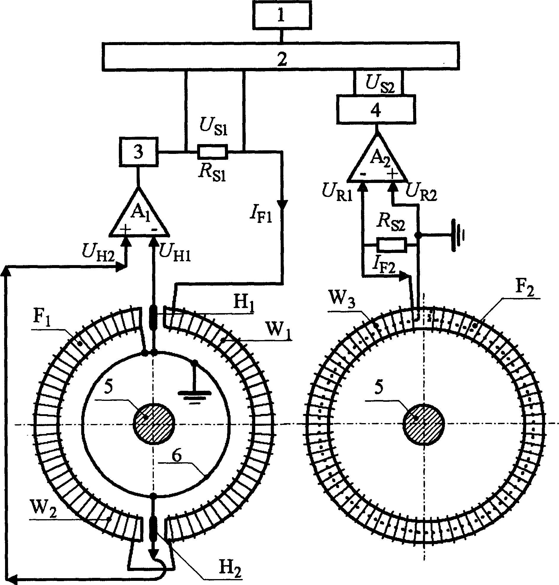
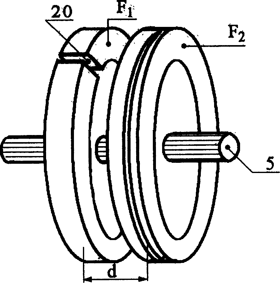
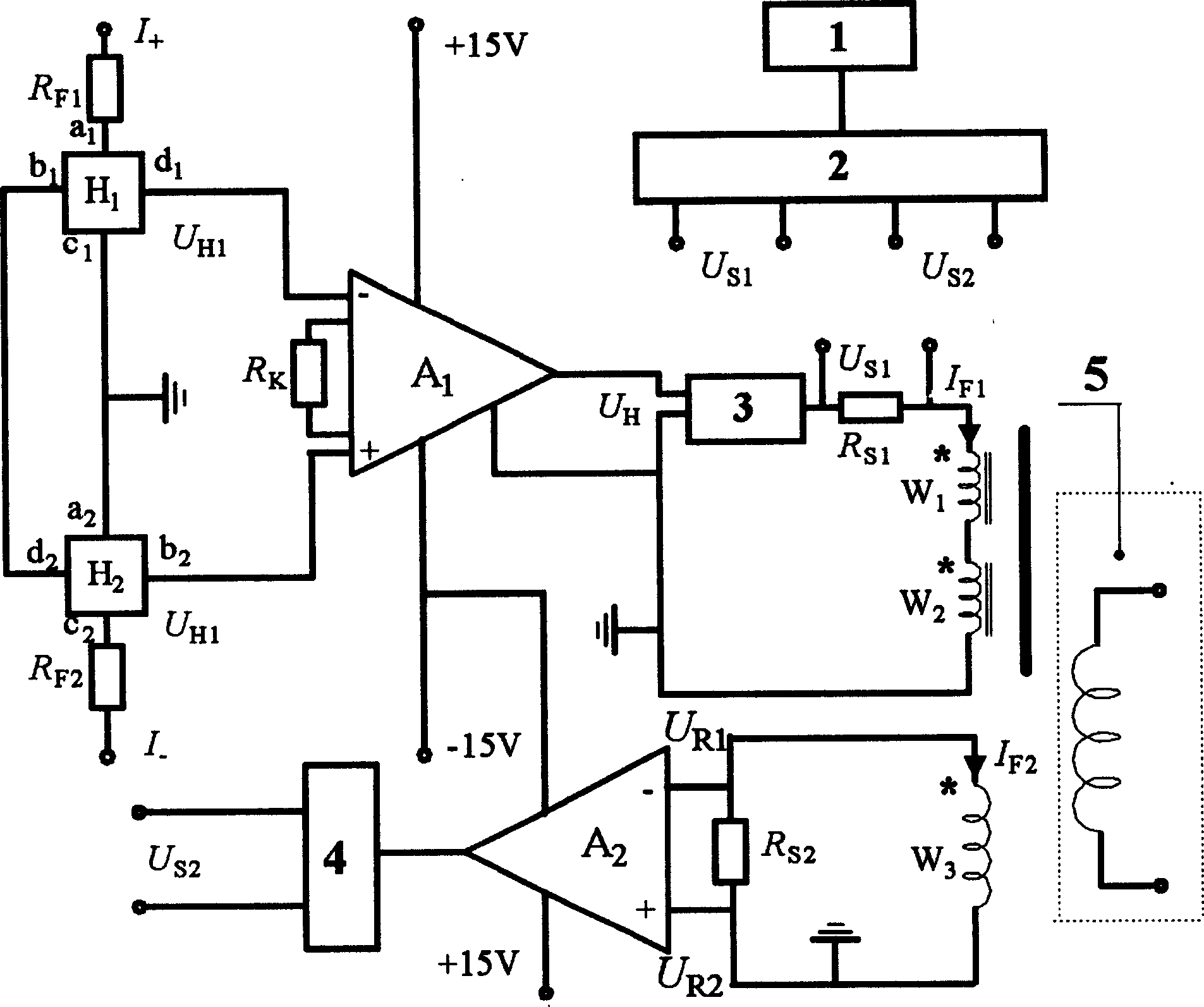
[0026] As shown in Figure 1(a), 1 is a display, 2 is a computer for processing detection voltage signals from two groups of parallel channels; 3 is processing the filtering, voltage-current conversion, and Current amplifying circuit; 4 is a filtering and integral amplifying circuit for processing the induced voltage from the Rogowski coil detection element, and its output voltage is U S2 ; 5 is the measured current bus; 6 is the dedicated ground layer; F 1 and F 2 For two skeleton cores; A 1 and A 2 is the operational amplifier; R S1 and R S2 is the sampling resistance of two groups of detection channels; I F1 and I F2 is the current flowing in the two groups of detection channels; U S1 is the sampling resistor R S1 terminal voltage; U R1 and U R2 is the sampling resistor R S2 The terminal voltage, H 1 and H 2 are two Hall elements; U H1 and U H2 Hall voltage output by two Hall elements; W 1 and W 2 are the two feedback windings of the channel; W 3 for the Ro...


PUM


Abstract

The invention discloses a kind of current sensor, the character lies in: the feedback windings in the two symmetrical channels are connected in series, one end is accessed to the ground, the other end is accessed to one end of the sample resistance; the output of the symmetrical Hall elements are amplified, then carries on filter, voltage-current transform, current amplifying process, the output end is accessed to another end of the sample resistance, the detected voltage signal detected at two ends of the sample resistance; it also includes Rogowski coil, the two ends of the coil are connected in parallel to the sample resistance, the detected voltage signal of sample resistance is amplified, filtered and integral amplified, and transmitted to the computer; the computer process the data and transmits the detected current to the monitor to be displayed; the precision is higher than 0.5%. The power consumption is small, the temperature additional error is less than 0.1%/10 degrees centigrade, the structure is simple, and easy to be assembled, debugged and maintained.

Description

Technical field: [0001] The invention relates to a current sensor, which is especially suitable for current feedback, cut-off control, steady current regulation, and transient large current signal detection in DC side overcurrent and short circuit protection in power electronic equipment. Background technique: [0002] Accurate detection and control in frequency conversion speed control devices, inverter devices, UPS power supplies, inverter welding machines, substations, electrolytic plating, CNC machine tools, microcomputer monitoring systems, power grid monitoring systems and in various fields that require isolation and detection of large non-sinusoidal currents The non-sinusoidal large current is the fundamental guarantee for the safe and reliable operation of the equipment and the first problem to be solved. [0003] Now, large current measuring devices such as current comparators, current transformers, and shunts have been developed; some measuring devices based on phy...

Claims


Application Information

Patent Timeline
Patent Type & Authority Applications(China)
IPC IPC(8): G01R15/20G01R19/00G01R19/25
Inventor 李维波毛承雄陆继明范澍
Owner HUAZHONG UNIV OF SCI & TECH
Why Eureka
Try Eureka