
3-D machining method of micromechanical parts

A processing method and micro-mechanical technology, applied in the direction of computer control, instruments, simulators, etc., can solve the problems of few researches on nano-processing, no processing mechanism and related technologies, difficult processing, etc.

Inactive Publication Date: 2005-01-12
HARBIN INST OF TECH
View PDF0 Cites 25 Cited by
  • Summary
  • Abstract
  • Description
  • Claims
  • Application Information

AI Technical Summary

Problems solved by technology

[0003] 1. LIGA technology is derived from the semiconductor lithography process and uses photolithography to generate three-dimensional space micro-mechanical components at one time. Its disadvantages are: the X-ray synchrotron radiation source required by the LIGA process is relatively expensive and scarce, which makes its use restricted
4. RPM (Rapid Protyping / Part Manufacturing) technology: This technology adopts the principle of (software) discrete / (material) accumulation to manufacture parts, obtains the order, path, limit and method of accumulation through discrete, and "stacks" them through material accumulation Forming three-dimensional solids, the disadvantage of this technology is that the processing materials are limited, and it is mainly used for the processing of polymers
However, nanofabrication based on atomic force microscopy (AFM) diamond tips has not been studied much.
[0009] Disadvantages and deficiencies of the above methods: LIGA technology: expensive equipment, can only process two-dimensional or quasi-three-dimensional structures; three-beam processing: can only process quasi-three-dimensional structures; micro-electric discharge machining technology (EDM): requirements for processing materials Relatively strict, it is difficult to process non-conductors such as glass; RPM technology: limited processing materials, mainly used for polymer processing
However, the processing based on the scanning probe microscope is still limited to two-dimensional micro-patterns, and has not formed a complete set of processing mechanisms and related technologies similar to ultra-precision diamond turning.
In the mechanism research of nanofabrication using SPM, many process parameters do not have corresponding optimization data and curves

Method used


Image

  • 3-D machining method of micromechanical parts
  • 3-D machining method of micromechanical parts
  • 3-D machining method of micromechanical parts

Examples


specific Embodiment approach 1

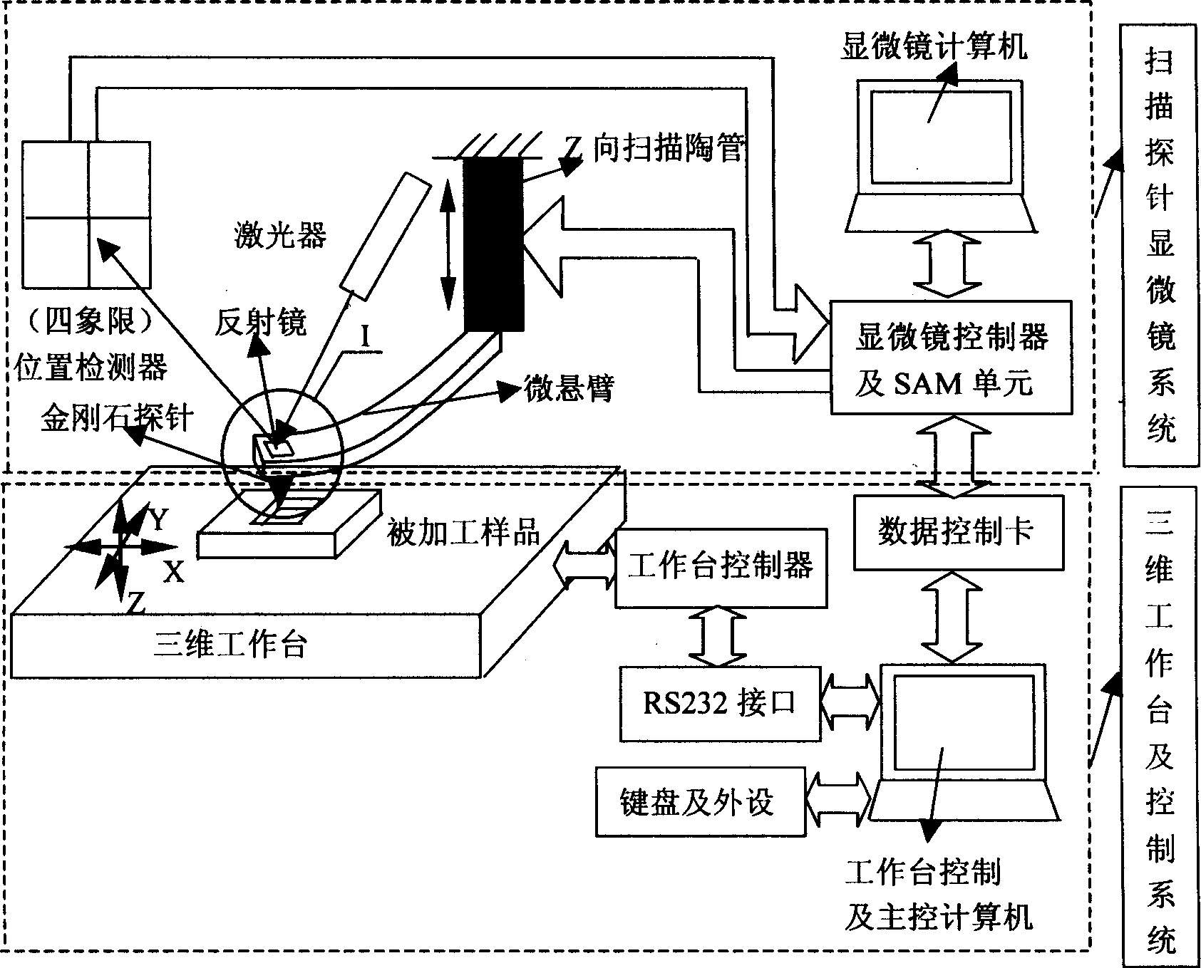
[0014] Specific Embodiment 1: This embodiment is a way to obtain a micro three-dimensional structure (or three-dimensional parts) by using SPM combined with a micro-motion three-dimensional workbench: by changing the shape and range of the SPM scan in the XY plane in the horizontal direction, and at the same time through the XY Moving the worktable in the plane can realize concave or convex three-dimensional structure processing. As shown in Figure 3, its processing sequence is as follows: the needle tip and the surface in section AB are in the processing state, and the needle tip and surface in section BC move downward in the Z direction of the worktable, so that the needle tip and the processed sample are separated from each other, so the surface is not processed. The CD section returns to the state of the AB section through the movement of the Z-direction worktable, and continues to process, thus completing the processing of the AB and CD sections and keeping the BC section ...

specific Embodiment approach 2

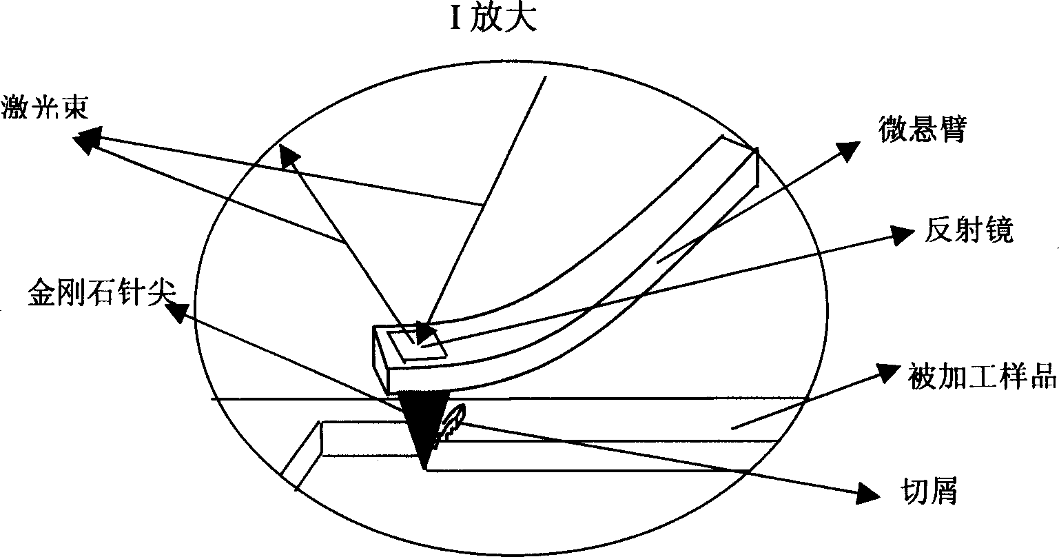
[0016] Specific implementation mode two: see figure 1 , put a single crystal copper sheet with smooth surface quality on the three-dimensional workbench. First adjust and set the SPM parameter value and the working parameters of the workbench, such as feed rate, scanning speed, Setpoint setting voltage representing the vertical pressure, and manually control the keyboard of the computer to control the controller of the SPM system to make the processing probe approach The sample, the probe reaches the sample and embeds on the surface of the sample, automatically stops after reaching the SPM setting value we selected, and drives the workbench to start scanning processing in the XY horizontal plane, and the Setpoint setting voltage representing the vertical pressure remains constant during processing. After processing a circle, figure or square groove A area (see Figure 4, that is, the AB section of Figure 3), the computer keyboard is manually controlled and the probe is lifted t...

specific Embodiment approach 3

[0017] Specific implementation mode three: this implementation mode is processing such as Figure 14 Processing steps for the graph shown: First, divide the graph to be processed into six rectangles in the horizontal direction, such as Figure 13As shown, the computer processes the graphics according to the pre-designed path: control the vertical movement of the three-dimensional worktable, so that the diamond tip is in contact with the workpiece and pressed into it. When the pressing force, that is, the preset tip load reaches the designed rectangle 1 After the machining depth is required, the computer controls the three-dimensional workbench to stop feeding in the vertical direction, and the X and Y directions of the workbench start to automatically process the rectangle 1. At this time, the computer controls the micro-motion three-dimensional worktable to move two-dimensionally through the program, and moves the rectangle 2 of the next processing area of ​​the workpiece to ...


PUM

PropertyMeasurementUnit
Surface roughnessaaaaaaaaaa

Abstract

The disclosed two methods are realized through combined micro machine parts 3D processing unit: setting up working parameters of sweeping probe microscope; placing workpiece on 3D table, fabricating first graph through XYLEM movement of controlled table, after finishing the first graph, raising probe up; fabricating second graph till completion. Another method includes steps: 3D table is moved in X, Y, Z directions according to presetting values to fabricate all graphs; contracting movement of scanning ceramics tube raises probe up. Comparing prior art, the disclosed method carries our real manufacturing. The method damages surface very little, only nano magnitude of material is removed, applicable to fabricating MEMS parts, masks and microminiature mould.

Description

technical field [0001] The invention belongs to an ultra-precision processing method, in particular to a three-dimensional processing method for micromechanical parts. Background technique [0002] The processing technology of micro-sized parts mainly has the following five methods: LIGA processing technology, three-beam processing technology, micro electric discharge machining technology (EDM), RPM (Rapid Protyping / Part Manufacturing) technology and processing technology based on scanning probe microscope. This paper mainly describes the status and development of micromachining based on scanning probe microscope. [0003] 1. LIGA technology is derived from the semiconductor lithography process and uses photolithography to generate three-dimensional space micro-mechanical components at one time. Its disadvantages are: the X-ray synchrotron radiation source required by the LIGA process is relatively expensive and scarce, which makes its use restricted. 2. Three-beam process...

Claims


Application Information

Patent Timeline
IPC IPC(8): G05B15/02G05B19/18G05B19/408
Inventor 阎永达孙涛赵清亮董申梁迎春胡振江
Owner HARBIN INST OF TECH
Learn More