
CO2 laser tube

A carbon dioxide and laser tube technology, applied in lasers, laser parts, phonon exciters, etc., can solve the problems of increasing user cost of laser processing equipment, pollution of total reflection mirrors and output mirrors, unstable electrochemical properties, etc. Achieve the effect of highlighting substantive features and progress, improving service life, and stable electrochemical properties

Inactive Publication Date: 2005-01-12
周迅
View PDF0 Cites 17 Cited by
  • Summary
  • Abstract
  • Description
  • Claims
  • Application Information

AI Technical Summary

Problems solved by technology

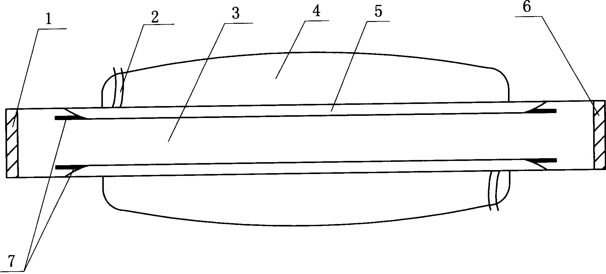
[0002] In the prior art, a carbon dioxide laser tube is generally composed of a discharge tube, a gas storage tube, a water cooling tube, an output mirror, a total reflection mirror, a cooling nozzle and an electrode, wherein the cooling nozzle, the discharge tube, the water cooling tube and the gas storage tube are made of glass Or quartz material, the total reflection mirror is generally made of glass, quartz or silicon wafer and other materials, and is made of gold plating by vacuum method. It is polished by materials such as zinc selenide, gallium arsenide or germanium; since the laser tube is filled with a certain proportion of CO 2 , N 2 , He and other working gases, the high-voltage electricity excites the working gas through the electrodes to make it output CO 2 Laser, the material and manufacturing process used in this carbon dioxide laser tube have been used for decades in our country. Since the electrode is made of metal materials such as silver or silver-copper alloy or nickel, these metal materials are especially unstable in electrochemical properties. Working at high voltage and high temperature, it will react with the gas in the gas storage tube. Once the gas reacts, it will change the gas composition in the gas storage tube. At the same time, under the action of high voltage and high temperature, the metal atoms will "splash" The "radiation" phenomenon pollutes the total reflection mirror and the output mirror, resulting in an extremely short working life. The most obvious manifestation is that the power of the laser tube continues to drop. Generally, when the power of the laser tube drops to 70% of its rated power, its The working time is only about 1500 hours, which greatly increases the cost of laser processing equipment users, and also restricts the application of lasers in industrialization

Method used


Image

  • CO2 laser tube

Examples


Embodiment Construction

[0007] Accompanying drawing has represented the embodiment of structure of the present invention and laser tube thereof, and its embodiment is described in detail below again, and this carbon dioxide laser tube includes discharge tube 3, gas storage tube 4, water cooling tube 5, output mirror 6, The total reflection mirror 1 and the electrode 7, the discharge tube 3 and the water-cooled tube 5 are placed in the gas storage tube 4, the water-cooled tube 5 is sleeved on the discharge tube 3, and the cooling water nozzle 2 is set on the water-cooled tube 3 to feed water The two ends of the gas storage tube 4 are welded with the water-cooled tube 5, and the electrode 7 is made of titanium or titanium alloy. It can be processed. The manufacturing method of the whole laser tube is the same as in the prior art. The electrodes are electrically connected to the DC power supply, and the titanium or titanium alloy excites the gas in the discharge tube under the action of the DC power supp...


PUM


Abstract

The disclosed laser tube includes discharge tube, gas storage tube, water-cooling tube, output mirror, total reflection mirror and electrodes. The said discharge tube, water-cooling tube are installed inside gas storage tube, and the water-cooling tube sheaths the discharge tube. Characters are that the said electrodes are made from titanium or titanium alloy so as to delay change of gas composition in gas storage tube, reduce pollution to total reflection mirror and output mirror, and prolong service life of laser tube. Comparing with prior art, service life of the disclosed laser tube is prolonged at least 3.5 times.

Description

【Technical field】 [0001] The invention relates to an improved invention of a carbon dioxide laser tube, in particular to the invention of the electrode material in the laser tube. 【Background technique】 [0002] In the prior art, a carbon dioxide laser tube is generally composed of a discharge tube, a gas storage tube, a water cooling tube, an output mirror, a total reflection mirror, a cooling nozzle and an electrode, wherein the cooling nozzle, the discharge tube, the water cooling tube and the gas storage tube are made of glass Or quartz material, the total reflection mirror is generally made of glass, quartz or silicon wafer and other materials, and is made of gold plating by vacuum method. It is polished by materials such as zinc selenide, gallium arsenide or germanium; since the laser tube is filled with a certain proportion of CO 2 , N 2 , He and other working gases, the high-voltage electricity excites the working gas through the electrodes ...

Claims


Application Information

Patent Timeline
IPC IPC(8): H01S3/038
Inventor 周迅
Owner 周迅
Learn More