Color liquid crystal display devices

A liquid crystal display device, color technology, applied in light guides, optics, instruments, etc., can solve the problems of not considering color filters, NTSC ultra-high color purity, weak light emission, etc.

Inactive Publication Date: 2005-02-09
MITSUBISHI CHEM CORP
View PDF21 Cites 5 Cited by
  • Summary
  • Abstract
  • Description
  • Claims
  • Application Information

AI Technical Summary

Problems solved by technology

[0014] Therefore, in order to make the NTSC ratio greater than or equal to 80%, the backlight must be improved, but this alone is not sufficient, and the color filter that splits the light from the backlight into each pixel color must be improved in combination with the improvement of the backlight.
As an example, the usual phosphors for green light have a main luminescence peak at 540-550nm. Considering the light utilization efficiency, when adjusting the color material, increase the green pixel of the color filter as much as possible in this wavelength range. light transmittance, and can efficiently absorb the light emitted by the phosphor for blue light and the phosphor for red light, but when the wavelength of green light emitted by the backlight changes, for the green pixels of the same color filter, this balance was destroyed
In addition, for red pixels and blue pixels, the luminescence has been relatively weak so far. Even if the color filter does not strongly absorb the light emitted by the backlight, in order to obtain a state of luminescence in the wavelength region, it is necessary to adjust the color accordingly. material
[0015] Therefore, for example, in Japanese Patent Laid-Open No. 9-97017, phosphors with luminescence peaks not at 470 to 510 nm are used as backlight sources. Like the present invention, the luminescence spectrum of the phosphors is different from that of the usual green phosphors, but Ultra-high color purity with an NTSC ratio of 80% or more cannot be achieved because an appropriate color filter for the combined use of this light source is not considered
[0016] Therefore, although the emission wavelength of the backlight has been improved, it is impossible to achieve ultra-high purity with an NTSC ratio of 80% or more, or even 90% or more, by using the conventional color filter as it is.
[0017] On the other hand, for red pixels, the problem of secondary emission is also obvious
That is to say, in conventional phosphors, the emission peak of red light is at the wavelength of 610nm, and the secondary emission generated by the green phosphor is around the wavelength of 585-590nm. It is necessary to determine the contrast of light transmittance, and the color materials such as pigments and dyes currently available in the industry cannot obtain sufficient contrast in this wavelength region, so in order to obtain red pixels with high color purity, a large number of pigments have to be sacrificed. Brightness
[0018] Moreover, the chromaticity of the standard red pixel currently used is the type with the strongest red feeling (weak yellow feeling), although it is near the chromaticity (0.65, 0.33) of the CIE XYZ chromaticity system, but a red pixel pair with a stronger red feeling is used It is still effective to expand the range of color reproduction
However, making a red pixel feel red would darken the pixel
In other words, the current status quo is that red pixels have to strike a balance between brightness and color reproduction range
[0019] In addition, in conventional backlights with red phosphors having a luminescence peak around 610 nm, the purity of red is insufficient, making it difficult to reproduce very deep red images.

Method used


Image

  • Color liquid crystal display devices
  • Color liquid crystal display devices
  • Color liquid crystal display devices

Examples


manufacture example 1

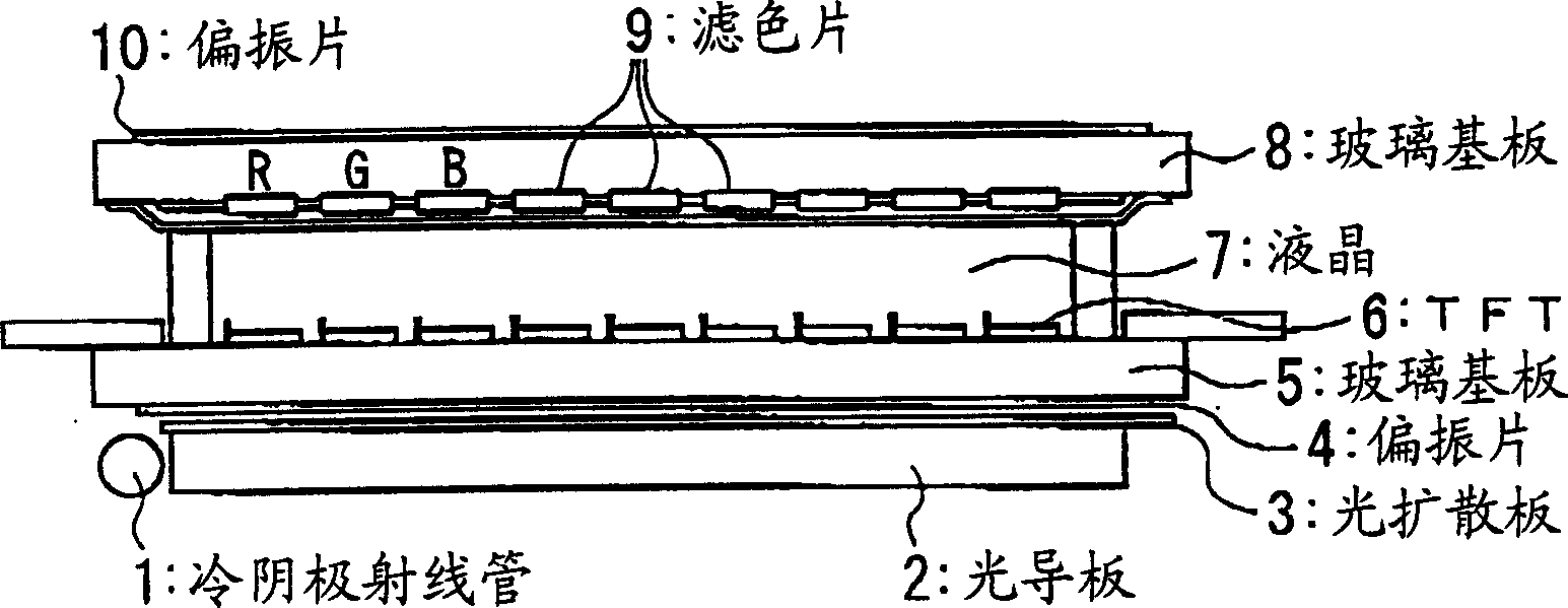
[0247] Manufacturing example 1: Manufacturing of backlight ①

[0248] 52 parts of red phosphor Y 2 o 3 : Eu (manufactured by Kasei Optonics Co., Ltd., trade name "LP-RE1"), 18 parts of Ba 0.9 Eu 0.1 O·(Mg 0.79 mn 0.21 )O·5Al 2 o 3 The green phosphor BaMgAl 10 o 17 : Eu, Mn (manufactured by Kasei Kodenshi Corporation, trade name "LP-G3") and 30 parts of blue phosphor BaMgAl 10 o 17: Eu (manufactured by Kasei Optoelectronics Co., Ltd., trade name "LP-B4"), mixed with nitrocellulose varnish into butyl acetate, fully mixed to make phosphor slurry, and coating the slurry on a tube with a diameter of The inner wall of the 2.3mm glass tube is dried and baked at 620°C for 5 minutes. Then, electrode mounting, evacuation, introduction of Hg and gas, sealing, etc. were carried out in the usual procedure to obtain a cold cathode ray tube for backlight.

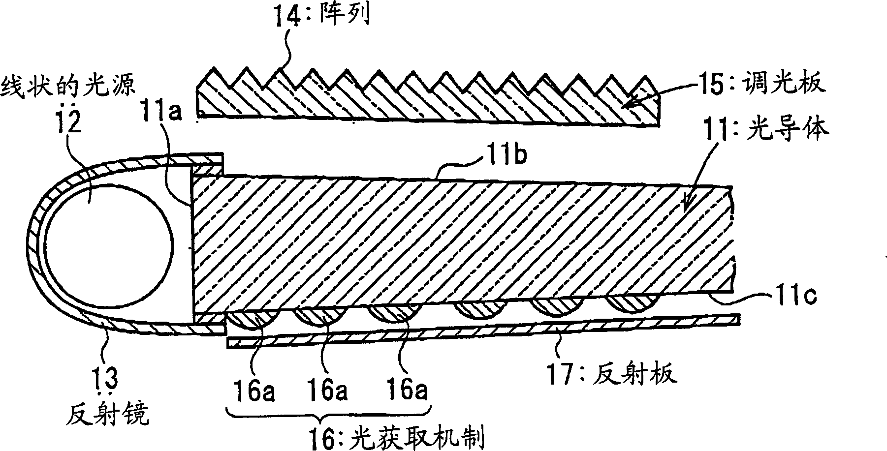
[0249] Subsequently, as a photoconductor, a wedge-shaped annular polyolefin resin plate (manufactured by Geon Corporation, J...

manufacture example 2

[0254] Manufacturing example 2: Manufacturing of backlight ②

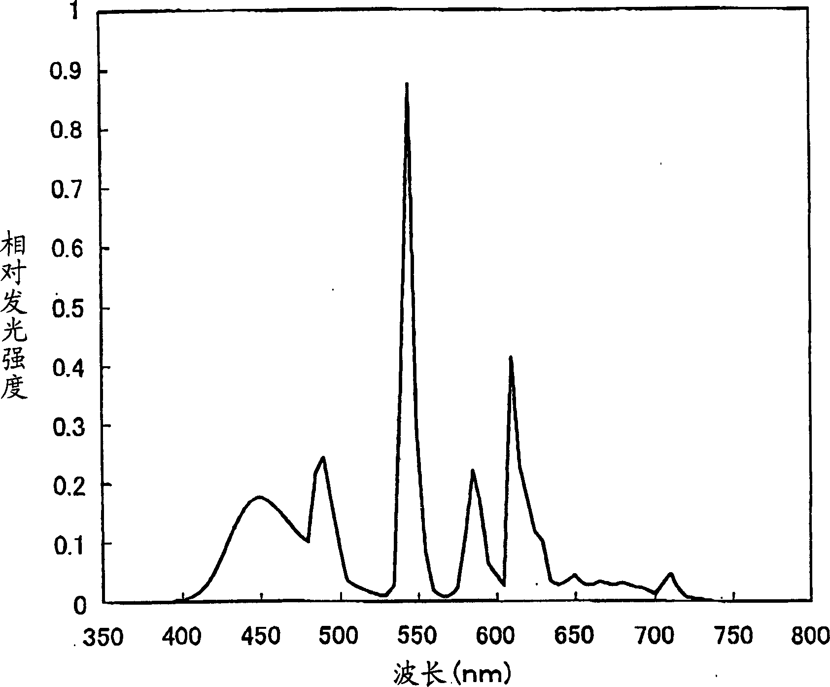
[0255] Using 40 parts by weight of red phosphor YVO 4 :Eu 3+ quasi-phosphor (manufactured by Kasei Photonics, trade name "MGV-620"), 22 parts by weight of green phosphor LaPO 4 : Ce, Tb phosphor (manufactured by Kasei Kodenshi Corporation, trade name "LP-G2") and 38 parts by weight of blue phosphor BaMgAl 10 o 17 : Eu (manufactured by Kasei Photonics Co., Ltd., trade name "LP-B4"), except that, it was produced in the same manner as in Production Example 1 to obtain a cold cathode ray tube for backlight, which was processed in the same manner as in Production Example 1 , get the backlight ②. The resulting relative luminescence spectra of the backlight are shown in Figure 6 .

[0256] The main emission wavelengths of the backlight ② are red: about 620 μm, blue: about 450 μm, and green: about 545 μm.

manufacture example 3

[0257] Manufacturing example 3: Manufacturing of backlight ③

[0258] Using 40 parts by weight of red phosphor YVO 4 :Eu 3+ quasi-phosphor (manufactured by Kasei Photonics, trade name "MGV-620"), 22 parts by weight of Ba 0.9 Eu 0.1 O·(Mg 0.79 mn 0.21 )O·5Al 2 o 3 The green phosphor BaMgAl 10 o 17 : Eu, Mn (manufactured by Kasei Kodenshi Corporation, trade name "LP-G3") and 38 parts by weight of blue phosphor BaMgAl 10 o 17 : Eu (manufactured by Kasei Photonics Co., Ltd., trade name "LP-B4"), except that, it was produced in the same manner as in Production Example 1 to obtain a cold cathode ray tube for backlight, which was processed in the same manner as in Production Example 1 , get the backlight ③. The resulting relative luminescence spectra of the backlight are shown in Figure 7 .

[0259] The main emission wavelengths of the backlight ③ are red: about 620 μm, blue: about 450 μm, and green: about 515 μm.


PUM

PropertyMeasurementUnit
thicknessaaaaaaaaaa
diameteraaaaaaaaaa
diameteraaaaaaaaaa

Abstract

There are provided color liquid crystal display devices with high color purity of NTSC percentage of at least 80%. A color liquid crystal display device comprises a combination of light shutters utilizing a liquid crystal 7, a color filter 9 having color elements of at least three colors of red, green and blue corresponding to the light shutters, and a backlight 1, 2 for transmission illumination. Under the following definitions: T(lambdan) represents a spectral transmittance at a wavelength lambdan nm (a wavelength at every 5 nm in the visible light region of from 380 to 780 nm) by a green pixel of the color filter 9; and I(lambdan) a relative emission intensity, normalized by a total emission intensity, at a wavelength lambdan nm from the backlight, these satisfy the following conditions (1) to (3): (1) at one wavelength in 500 nm(lambdan)>0.01; (2) in a wavelength region of 610 nm(lambdan)<0.0001; (3) in a wavelength region of 400 nm(lambdan)<0.0001.

Description

technical field [0001] The first item of the present invention relates to a color liquid crystal display device, in particular to a color liquid crystal display device that can realize a high color purity of NTSC (National Television System Committee) ratio greater than or equal to 80%, or even greater than or equal to 90%. The liquid crystal display device is composed of a combination of a liquid crystal optical shutter, a color filter corresponding to the optical shutter, and a backlight for transmission illumination, and the color filter has at least three primary colors of red, green, and blue; the color liquid crystal display device By improving the luminous wavelength of the backlight and adjusting the transmittance of the color filter corresponding to the luminous wavelength of the backlight, especially adjusting the spectral transmittance of the color filter to the green pixel, to achieve a green pixel with high color purity, thereby reproducing a certain Depth of gree...

Claims


Application Information

Patent Timeline
Patent Type & Authority Applications(China)
IPC IPC(8): G02B5/20G02F1/1335G02F1/13357
CPCG02B6/004G02F1/133514G02B6/0038G02F1/133615G02B6/0036G02F2001/133607G02B5/201G02F1/133607G02B6/0001G02F1/1335
Inventor 川名真迫直树木岛直人久宗孝之大塚礼治
Owner MITSUBISHI CHEM CORP
Why Eureka
Try Eureka