Metal ion implantation machine

A technology of metal ion implantation and metal ion source, applied in ion implantation plating, metal material coating process, coating, etc., can solve the problems of high beam extraction voltage, long injection time, small injection area, etc. Effect of high peeling rate, short injection time, and low injection temperature

Inactive Publication Date: 2005-04-27
珠海市恩博金属表面强化有限公司
View PDF0 Cites 11 Cited by
  • Summary
  • Abstract
  • Description
  • Claims
  • Application Information

AI Technical Summary

Problems solved by technology

[0004] At present, there are ion implanters in the world that apply this technology to surface treatment of workpieces. However, the existing ion implanters used in industry have weak ion beam currents, high beam extraction voltage, and small implantation areas. The injection time is longer, such as the Z-100 and Z-200 injection machines in the United States, the injection area is 250cm 2 , the GLZ-100 industrial ion implanter for metals of the Southwest Institute of Physics of my country's nuclear industry, the implantation area is 300cm 2 , their injection time is 90 minutes to 2 hours, and the beam extraction voltage is greater than 50kv, so the processing cost of the workpiece is too high

Method used


Image

  • Metal ion implantation machine
  • Metal ion implantation machine
  • Metal ion implantation machine

Examples


Embodiment Construction

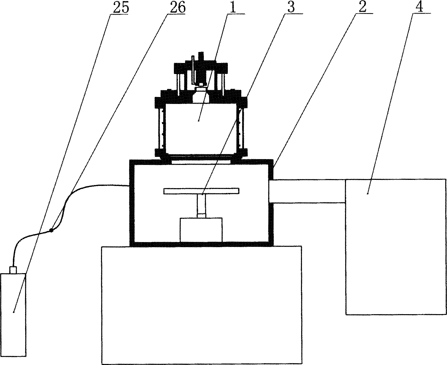
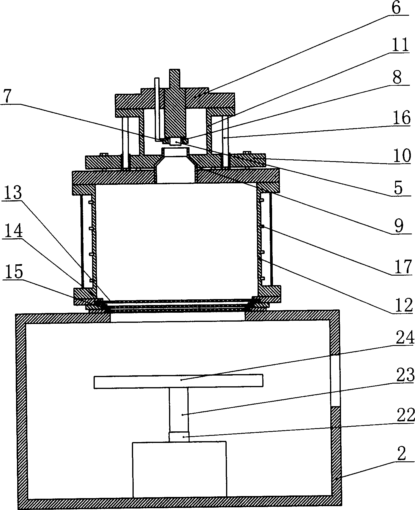
[0015] like figure 1 , figure 2 As shown, the present invention includes a metal ion source 1, an ion source power supply system, a vacuum chamber 2, a workpiece target stage 3, a motor 22, a vacuum system 4, a cooling system, a nitrogen source 25, a mass flow valve 26 and a control panel.

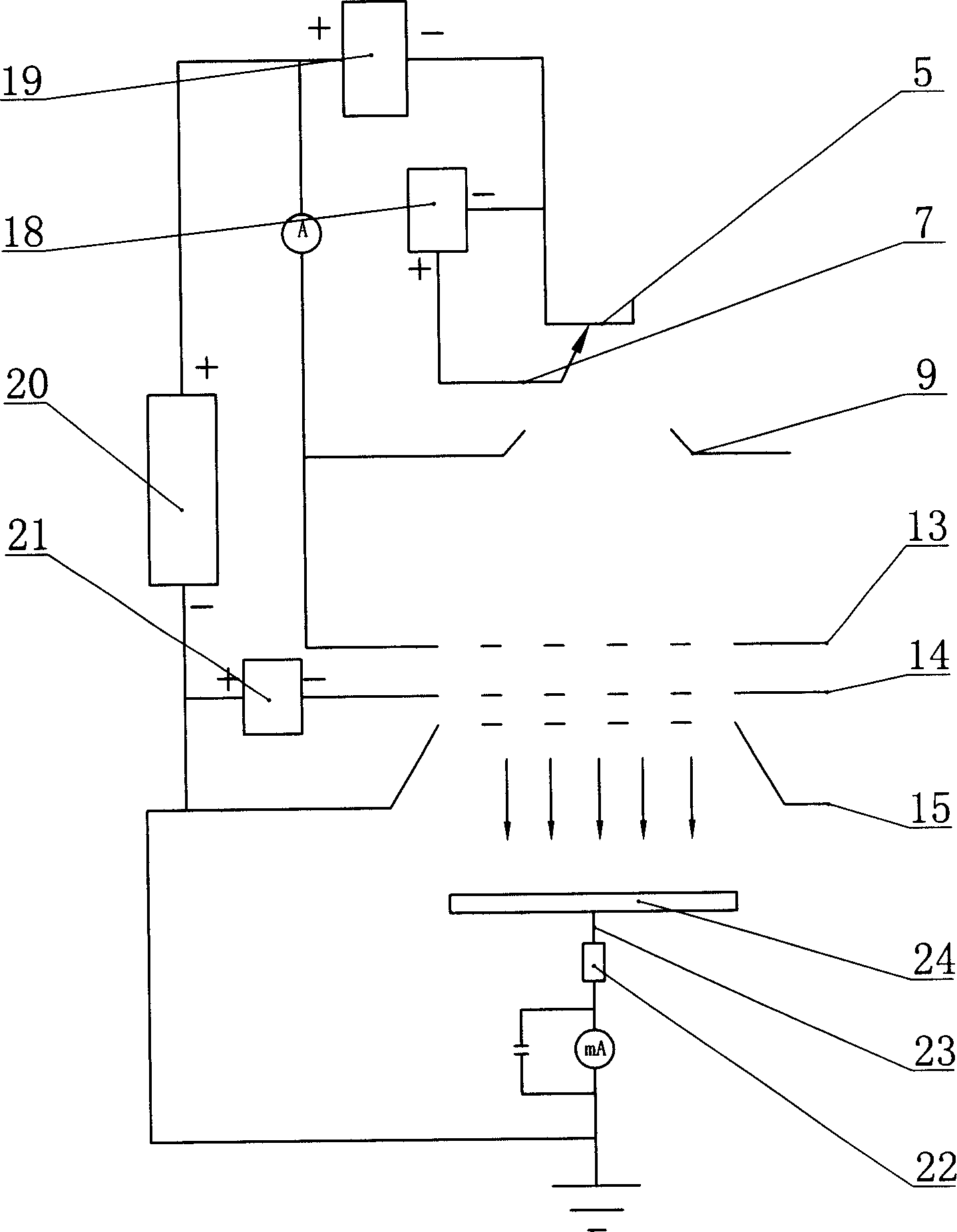
[0016] The metal ion source 1 is arranged on the upper part of the vacuum chamber 2 and communicated with the vacuum chamber 2 . The metal ion source includes a cathode 5, a cathode support 6, a trigger electrode 7, an insulating cathode casing 8, an anode 9, an anode support 10, a discharge chamber 11, a plasma chamber 12, a first grid 13, a second grid 14 and a third grid. Grid 15, the trigger electrode 7 is separated by the insulating cathode sleeve 8 and placed on the outer periphery of the cathode 5, the upper end of the discharge chamber 11 is connected to the cathode support 6, and the lower end is connected to the anode support 10, The outer periphery of the discharge chamber 11...


PUM


Abstract

The present invention is one metal ion implanter with strong ion beam flow, low ion beam leading out voltage, great ion beam implanting area, short ion implanting period and low workpiece treating cost. The metal ion implanter has metal ion comprising cathode, cathode rack, triggering electrode, insulating cathode sleeve, anode, anode rack, charge chamber, plasma chamber, the first grid, the second grid and the third grid. The interval between the first grid and the second grid is 5-10 mm, and these three grids are 2-5 mm thick plates with 1300-1800 small holes each of 3-5 mm diameter. The arc voltage power source has characteristic impedance of 1 ohm, pulse width of 0.44-0.65 ms and frequency of 5-25 Hz. The present invention is used in the production of metal parts.

Description

technical field [0001] The invention relates to a metal ion implanter. Background technique [0002] Conventional surface treatment technology, because it needs to be carried out in a high temperature environment, will change the overall size and surface finish of the workpiece, so that it needs to be finished after heat treatment, so it cannot meet the requirements of use, and the heat treatment layer is prone to surface peeling and peeling phenomenon. [0003] Ion implantation technology is a high-tech material surface modification developed internationally in recent years. Its basic principle is: use an ion beam with an energy of tens to hundreds of keV to enter the material, the ion beam and the material A series of physical and chemical interactions will occur in the atoms or molecules in the material, and the incident ions will gradually lose energy, and finally stay in the material, causing changes in the surface composition, structure and ...

Claims


Application Information

Patent Timeline
Patent Type & Authority Applications(China)
IPC IPC(8): C23C14/48
Inventor 陶士慧马山明邵先华叶围洲蔡恩发蔡坚将吴观绵吴九妹
Owner 珠海市恩博金属表面强化有限公司
Why Eureka
Try Eureka