

Abrasion-resistant bearing of motor type fuel pump
A fuel pump, wear resistance technology, applied in the direction of bearings, shafts and bearings, bearing components, etc., can solve the problems of rapid wear, accelerated wear, and no wear resistance.
- Summary
- Abstract
- Description
- Claims
- Application Information
AI Technical Summary
Problems solved by technology
Method used
Image

Examples
Embodiment Construction
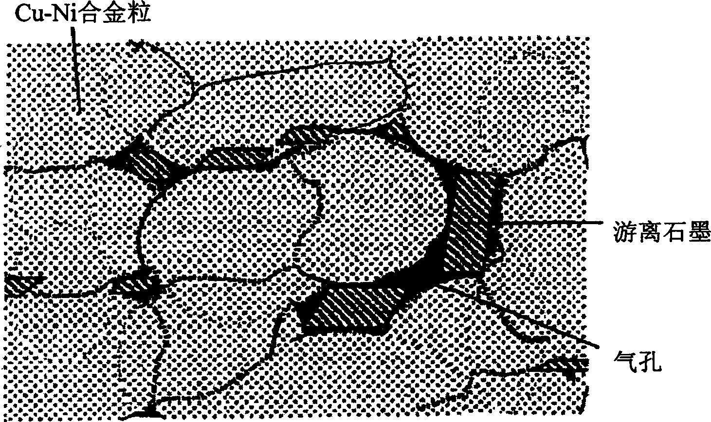
[0023] The bearing of the motor fuel pump of the present invention will be described more specifically based on an embodiment. As raw material powders, Cu-Ni alloy (Ni content ratios are shown in Tables 1 and 2) powders, Cu-P alloys (similarly, P content The ratios are shown in Tables 1 and 2) powder, graphite powder, Sn powder, Co powder, Fe powder, and Cu powder. These raw material powders are blended into the compounding compositions shown in Tables 1 and 2, and 1% of stearic acid is added. , after mixing for 20 minutes by a V-type mixer, stamping and forming a green compact with a predetermined pressure in the range of 400-500 MPa, the green compact is sintered at 870°C for 40 minutes in an ammonia decomposition gas atmosphere , In addition, finally, the sizing treatment is carried out at a predetermined pressure in the range of 400-500MPa, so as to manufacture Cu-Ni-based sintered alloys or Cu-based sintered alloys with porosities shown in Tables 1 and 2, respectively. T...
PUM
 Abstract
Description
Claims
Application Information