Repairing method for thin belt continuous casting crystallining roller
A technology of continuous casting crystallization and repair method, which is applied in the direction of non-electric welding equipment, welding equipment, metal processing equipment, etc., can solve the problems of increasing the difficulty of repair work, achieve high repair efficiency, improve bonding force, and eliminate the adsorption oxygen layer Effect
- Summary
- Abstract
- Description
- Claims
- Application Information
AI Technical Summary
Problems solved by technology
Method used
Image
Examples
Embodiment 1
[0038] (1) According to the surface wear of the crystallization roller and the design shape of the surface of the crystallization roller, determine the spraying thickness of each part on the surface, determine the amount of powder feeding during spraying and the spraying time of each area.
[0039] (2) Repair spraying: adopt the method of cold air power spraying, use compressed nitrogen to carry copper powder and spray on the surface of molten steel crystallization roller at supersonic speed, and repair the wear groove of crystallization roller. The particle diameter is 60-80μm.
[0040] Spraying pure Cu repair process: spraying distance 20mm, gas pressure 3.8-4MPa, gas temperature 200°C, gas flow rate 20g / s, metal powder impact speed 500m / s;
[0041](3) Repair inspection: check the size of the repaired surface after spraying, and the size is the same as the original design;
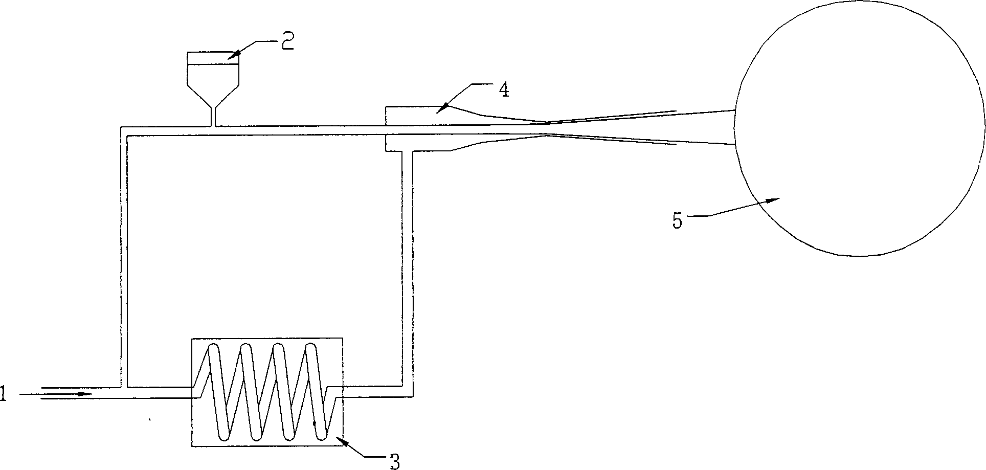
[0042] The structure of the cold air power spraying system is as follows: figure 1 As shown, the co...
Embodiment 2
[0047] The experimental procedure is the same as that of Example 1, except that the base material is steel. The selected material is BeZrNiCu, the particle diameter is 30-40μm, repair process: spraying distance 15mm, gas pressure 3.8MPa, gas temperature 600℃, gas flow rate 20-30g / s, metal powder impact speed 1100m / s.
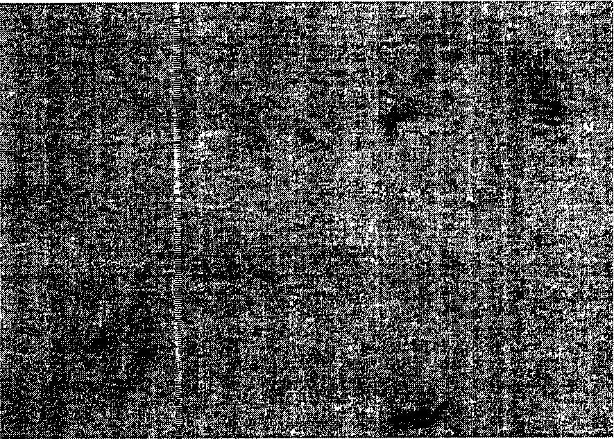
[0048] Figure 5 The SEM topography of the BeZrNiCu coating is shown, and the interface between the substrate and the coating is marked by an arrow. It can be seen that the coating is uniform and dense, and the interface is not obvious in high-magnification microscopic observation, indicating that the BeZrNiCu coating is in close contact with the steel substrate, forming a good thermal conductivity surface repair layer. It plays the role of repairing and forming a new repairing surface.
Embodiment 3
[0050] The experimental procedure is the same as in Example 1. The selected material is CrZrCu alloy, the diameter of the particles is: 20-30μm, the repair process: spraying distance 20mm, metal powder impact speed 500m / s, gas pressure 2.5MPa, gas temperature room temperature, gas flow rate 30g / s;
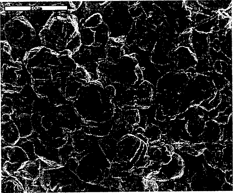
[0051] Image 6 The SEM topography of the CrZrCu coating is shown, and the interface between the substrate and the coating is marked by an arrow. It can be seen that the coating is uniform and dense, and the interface is not obvious in high-magnification microscopic observation, indicating that the CrZrCu coating is in close contact with the Cu substrate, forming a good thermal conductivity surface repair layer. It plays the role of repairing and forming a new repairing surface.
PUM
| Property | Measurement | Unit |
|---|---|---|
| Diameter | aaaaa | aaaaa |
| Diameter | aaaaa | aaaaa |
Abstract
Description
Claims
Application Information
 - R&D
- Intellectual Property
- Life Sciences
- Materials
- Tech Scout
- Unparalleled Data Quality
- Higher Quality Content
- 60% Fewer Hallucinations
Browse by: Latest US Patents, China's latest patents, Technical Efficacy Thesaurus, Application Domain, Technology Topic, Popular Technical Reports.
© 2025 PatSnap. All rights reserved.Legal|Privacy policy|Modern Slavery Act Transparency Statement|Sitemap|About US| Contact US: help@patsnap.com


