Production method of anode copper ball for electroplating and anode copper ball

A technology of anode copper ball and manufacturing method, applied in printed circuit manufacturing, electrodes, metal rolling, etc., can solve the problems of reducing filling rate, increasing manufacturing cost, poor yield of raw materials, etc., reducing manufacturing cost, improving positive The effect of sphericity and yield improvement

Active Publication Date: 2006-10-04
MITSUBISHI MATERIALS CORP
View PDF1 Cites 7 Cited by
  • Summary
  • Abstract
  • Description
  • Claims
  • Application Information

AI Technical Summary

Problems solved by technology

[0015] However, when forging is performed without oil supply, if the filling rate in the die is increased and the forging material is strongly pressed against the inner wall surface of the die, it will be difficult to remove the forging material from the die, so it is necessary to reduce the filling rate.
In the method described in Patent Document 1, when the ball is formed by cold forging with a low filling rate, there is a problem that the mold cannot be formed into a ball because the copper is not sufficiently filled.
[0016] In addition, in Patent Document 1, ring-shaped burrs are formed on the peripheral surface of the spherical material, and it is necessary to remove the burrs by cutting or the like. However, since cutting oil is used during cutting, it is not suitable for electroplating to avoid oil contamination. Forming with copper balls
In addition, because of deburring, there is a problem that the yield of raw materials is poor and the manufacturing cost increases.

Method used


Image

  • Production method of anode copper ball for electroplating and anode copper ball
  • Production method of anode copper ball for electroplating and anode copper ball
  • Production method of anode copper ball for electroplating and anode copper ball

Examples


Embodiment 1

[0068] An evaluation experiment was conducted to confirm the effects of the present invention. The result is shown below. In Comparative Experiment 1, the surface oil amount of the anode copper ball for electroplating was evaluated. As an example of the present invention, the anode copper ball for electroplating manufactured by the manufacturing method of the said embodiment was provided for the test. As Comparative Example 1, an anode copper ball for electroplating manufactured by forging while supplying oil was provided for the test.

[0069] These anode copper balls for electroplating were immersed in solvent H997 (Horiba Manufacturing Co., Ltd.), the oil on the surface of the anode copper balls for electroplating was extracted, and the solvent H997 was measured by FT-IR (Fourier Transform Infrared Spectrophotometer). H-C combination was evaluated as an oil component.

[0070] The evaluation results are shown in Table 1.

[0071] Oil

[0072]The amount of oi...

Embodiment 2

[0074] Next, in Comparative Example 2, the amount of sludge was evaluated. As an example of the present invention, the anode copper ball for electroplating manufactured by the manufacturing method of the said embodiment was provided for the test. As Comparative Example 2, an anode copper ball for electroplating manufactured by rolling was provided for the test.

[0075] Suspend an anode copper ball with a diameter of 55mm on a Ti rod, and use a brass plate as the cathode in a sulfuric acid bath with an electroplating solution volume of 1500ml and an electroplating solution temperature of 30°C. The surface area of ​​the cathode is 0.95dm 2 , cathode surface area 0.6dm 2 , the current value was kept at 3.6 mA, and electrolytic plating was performed for 24 hours. The sludge deposited on the bottom of the electrolytic cell was collected and dried, and the weight of the sludge was measured for evaluation.

[0076] The evaluation results are shown in Table 2.

[0077] ...


PUM


Abstract

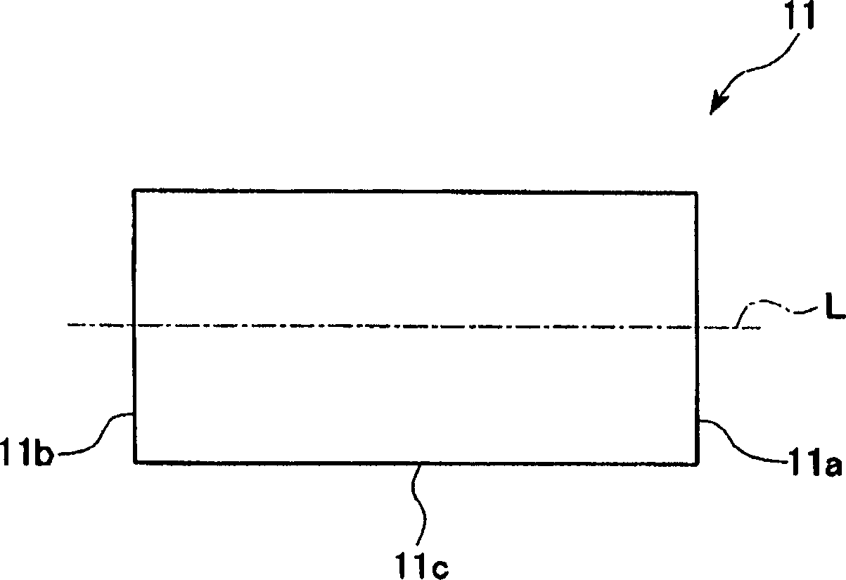
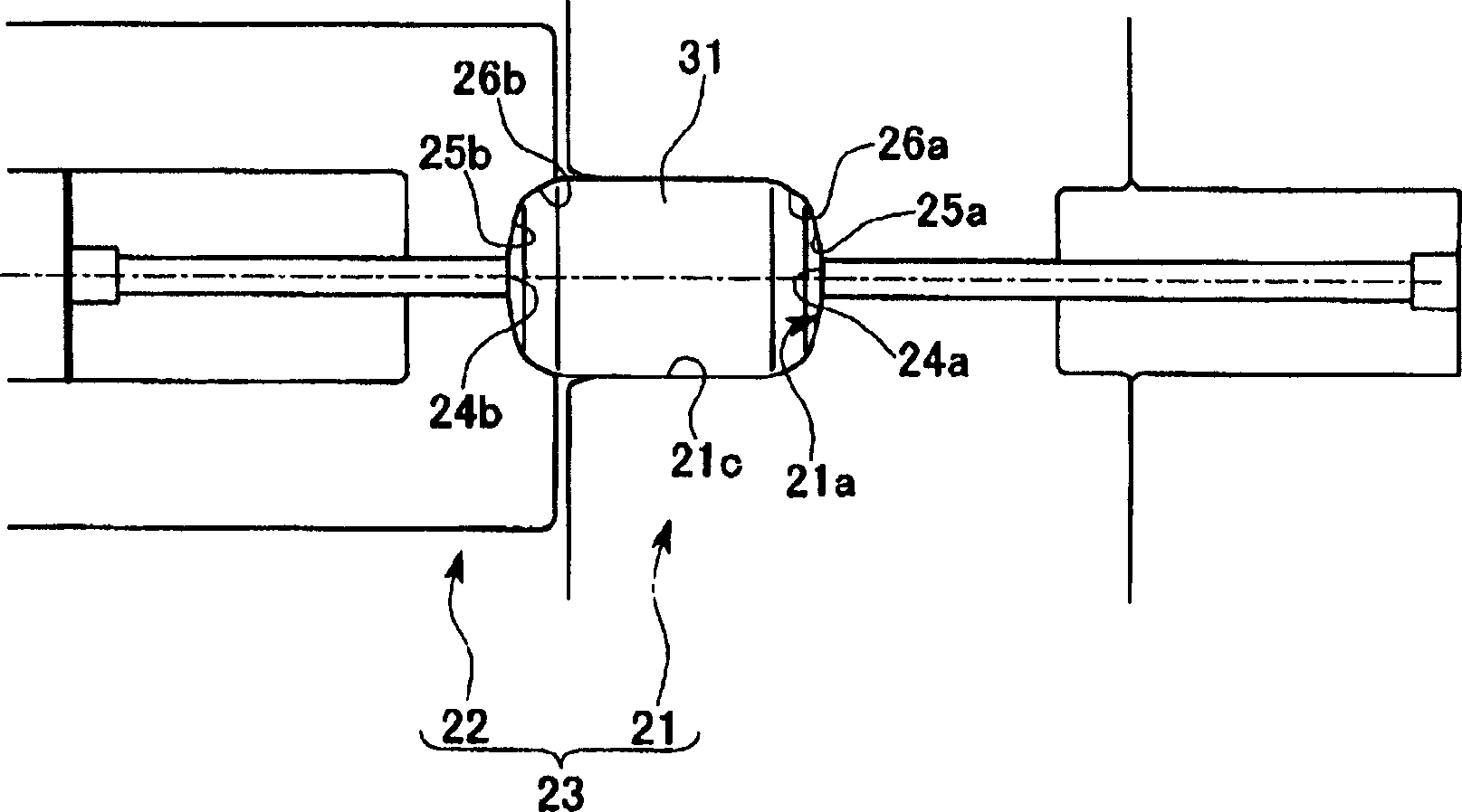
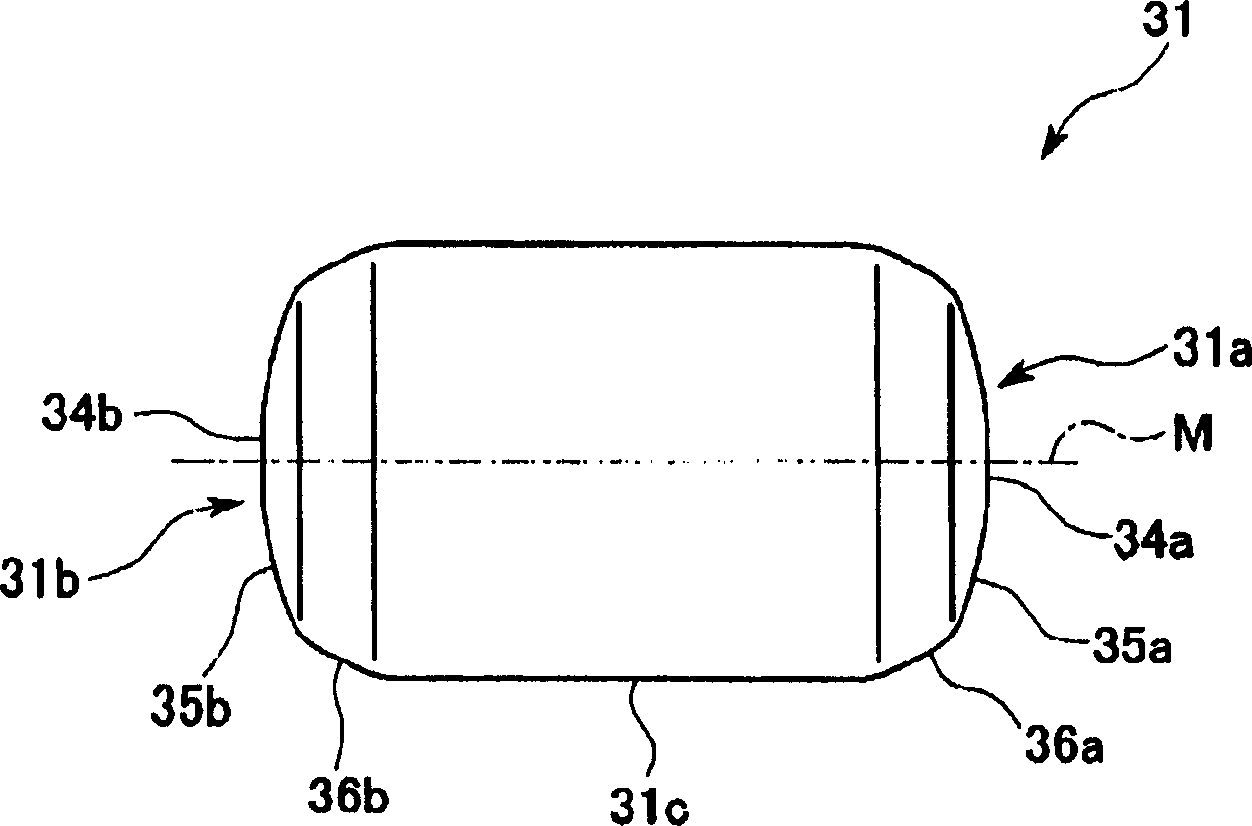
The present invention provides a method for manufacturing anode copper balls for electroplating. When forming an anode copper ball for electroplating by forging without oil supply, it can be stably manufactured, and the flat surface existing on the surface can be reduced as much as possible to manufacture rolling balls. Anode copper balls with good electroplating properties. As the manufacturing method of anode copper balls for electroplating, utilize the mold (23) that is made up of multiple sets of dies (21) and punching machine (22), carry out cold multi-stage forging to form balls from copper rods, wherein Connected to the inner wall surface of the die (21), the copper bar is forged in its axial direction, and the first intermediate material (31) is formed into a spherical shape through the first forging process. In the forging process, the outer circumference of the end surface is crushed As the first intermediate material (31) of the tapered surface.

Description

technical field [0001] The invention relates to a method for manufacturing an anode copper ball for electroplating, which is used as a copper raw material in copper electrolytic plating. Background technique [0002] Conventionally, as a method of electroplating copper on printed wiring boards such as mobile phones and computers, electrolytic plating in which copper is used as an anode and the printed wiring board is used as a cathode, dipped in a plating bath such as a dilute sulfuric acid solution, and current is widely used. This electrolytic plating is a method in which copper serving as an anode is melted in a dilute sulfuric acid solution, and copper plating is performed on the surface of a printed wiring board serving as a cathode. [0003] Furthermore, a constitutional method has been proposed in which, as the anode of the copper raw material for electrolytic plating, a spherical copper material (anode copper ball for electroplating) is used, and an electroplating ba...

Claims


Application Information

Patent Timeline
Patent Type & Authority Applications(China)
IPC IPC(8): B21K1/02B21J5/00C25D17/10
CPCC25D17/10H05K3/241B21B2003/005B21J5/00Y10T29/49204Y10T29/49218Y10T29/4998C25D17/12
Inventor 泷泽英男野村章二柚木雅纪
Owner MITSUBISHI MATERIALS CORP
Why Eureka
Try Eureka