Organic complex and organic electroluminescent display device employing same
A technology for display devices and organic light-emitting layers, applied in the field of materials used as hole transport layers, can solve the problems of material decomposition and cracking, taking a long time, and decreasing yield of sublimation purification
- Summary
- Abstract
- Description
- Claims
- Application Information
AI Technical Summary
Problems solved by technology
Method used
Image

Examples
no. 1 example
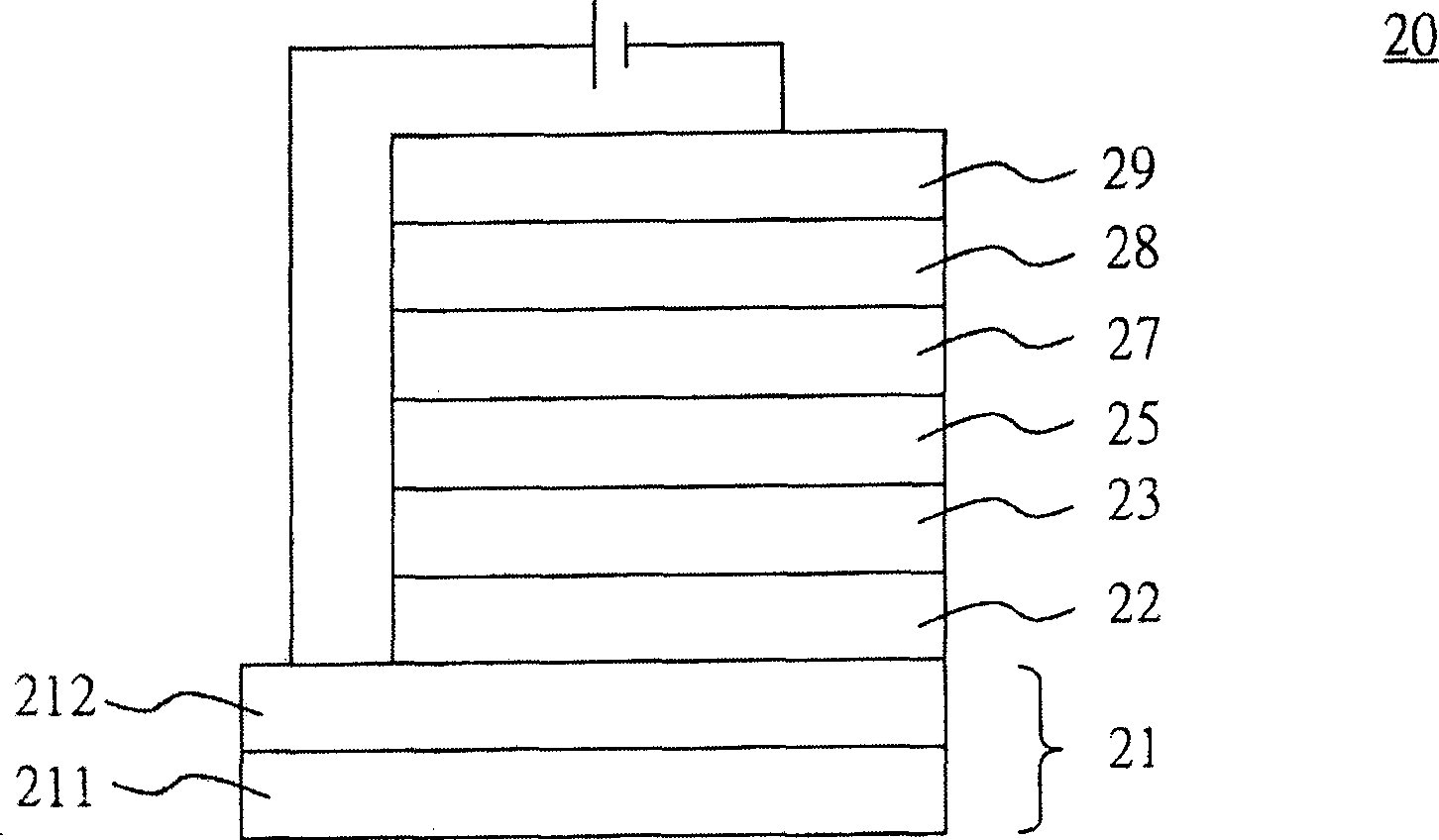
[0088] figure 2 is a schematic diagram showing the organic electroluminescence display device of the first embodiment of the present invention. Wherein, the metal complex A (Ir-ppz1) is used as the dopant of the light-emitting layer in the display device.
[0089] Such as figure 2 As shown, the organic electroluminescence device 20 mainly includes an anode (anode) 21 , an organic light emission layer (light emission layer, EML) 25 and a cathode (cathode) 29 . The anode 21 is, for example, coated with a layer of transparent and conductive indium tin oxide (ITO) 212 on the glass substrate 211 . The cathode 29 is, for example, a composite metal layer composed of lithium fluoride (LiF) and aluminum (Al). A hole injection layer (hole injection layer, HIL) 22 and a hole transport layer (hole transfer layer, HTL) 23 are further included between the organic light emitting layer 25 and the anode 21, and an electron transport layer is further included between the organic light emit...
no. 2 example
[0103] Figure 9 A schematic diagram showing an organic electroluminescent display device according to a second embodiment of the present invention. Wherein, the metal complex A (Ir-ppz1) is used as the material of the electron blocking layer (electron blocking layer, EBL) between the light emitting layer and the hole transport layer.
[0104] Such as Figure 9 As shown, the organic electroluminescent device 90 mainly includes an anode 91 , an organic light emitting layer (EML) 95 and a cathode 99 . The anode 91 is, for example, coated with a layer of transparent and conductive indium tin oxide (ITO) 912 on a glass substrate 911 . The cathode 99 is, for example, a composite metal layer composed of lithium fluoride (LiF) and aluminum (Al). A hole injection layer (HIL) 92 , a hole transport layer (HTL) 93 and an electron blocking layer 94 are further included between the organic light emitting layer 95 and the anode 91 . An electron transport layer (ETL) 97 and an electron i...
no. 3 example
[0152] Please refer to the schematic diagram of the organic electroluminescent display device of the third embodiment of the present invention figure 2 . Such as figure 2 As shown, the organic electroluminescent device 20 mainly includes an anode 21 , an organic light emission layer (light emission layer, EML) 25 and a cathode 29 . The anode 21 is, for example, coated with a layer of transparent and conductive indium tin oxide (ITO) 212 on the glass substrate 211 . The cathode 29 is, for example, a composite metal layer composed of lithium fluoride and aluminum (Al). A hole injection layer (hole injection layer, HIL) 22 and a hole transport layer (hole transfer layer, HTL) 23 are further included between the organic light emitting layer 25 and the anode 21, and an electron transport layer is further included between the organic light emitting layer 25 and the cathode 29 (electron transfer layer, ETL) 27 and electron injection layer (electron injection layer, EIL) 28 . Th...
PUM
| Property | Measurement | Unit |
|---|---|---|
| emission peak | aaaaa | aaaaa |
| emission peak | aaaaa | aaaaa |
| thickness | aaaaa | aaaaa |
Abstract
Description
Claims
Application Information
 - R&D
- Intellectual Property
- Life Sciences
- Materials
- Tech Scout
- Unparalleled Data Quality
- Higher Quality Content
- 60% Fewer Hallucinations
Browse by: Latest US Patents, China's latest patents, Technical Efficacy Thesaurus, Application Domain, Technology Topic, Popular Technical Reports.
© 2025 PatSnap. All rights reserved.Legal|Privacy policy|Modern Slavery Act Transparency Statement|Sitemap|About US| Contact US: help@patsnap.com