
Microstructured optical fiber with long wave cut-off function and preparation thereof

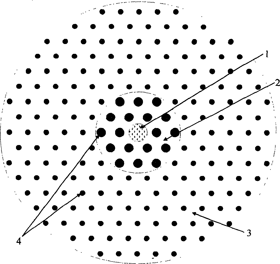
A micro-structured optical fiber and long-wave technology, applied in cladding optical fiber, optical waveguide, glass manufacturing equipment, etc., can solve the problems affecting the depth and width of the concave layer of the outer refractive index of the fiber core, affecting the performance of the optical fiber, and the difficulty of making the optical fiber. It is easy to control the refractive index, meet the requirements of practical applications, and have the effect of flexible design

Inactive Publication Date: 2006-10-11
NANKAI UNIV
View PDF0 Cites 18 Cited by
  • Summary
  • Abstract
  • Description
  • Claims
  • Application Information

AI Technical Summary

Problems solved by technology

However, the production of this kind of optical fiber is more difficult. Because the fluoride itself is corrosive, it is difficult to control the doping concentration and doping range of fluoride ions. If the doping concentration is inappropriate or the doping area is not strictly controlled, it will affect the fiber core The depth and width of the outer refractive index depression layer, which in turn affects the performance of the fiber

Method used


Image

  • Microstructured optical fiber with long wave cut-off function and preparation thereof
  • Microstructured optical fiber with long wave cut-off function and preparation thereof
  • Microstructured optical fiber with long wave cut-off function and preparation thereof

Examples


preparation example Construction

[0022] The preparation method of the long-wave cut-off microstructured optical fiber comprises the following two steps:

[0023] (1) Make the preform according to the design structure

[0024] Choose a high-purity quartz tube with a suitable diameter and wall thickness, and arrange a certain number of capillaries regularly in it. The size of the capillary is drawn according to the design requirements in advance, and a doped or non-doped solid quartz rod is used as the core in the center.

[0025] In this fabrication process, capillaries of at least two sizes need to be prepared, which are used to construct the refractive index depression layer and the cladding layer respectively.

[0026] (2) Wire drawing of the preform.

[0027] Using an ordinary commercial drawing tower, the preform is melted and drawn into an optical fiber at a high temperature of about 1800 ° C, and a UV-cured protective coating is coated on-line. The corresponding temperature of the melting rod is adopt...

Embodiment

[0036] image 3 It is an embodiment, a structural schematic diagram of constructing an S-band optical fiber amplifier with a long-wave cut-off microstructured optical fiber. The isolator 5, the erbium-doped long-wave cut-off microstructured fiber 7, the wavelength division multiplexing coupler 9, the semiconductor laser 10 and the isolator 11 form an S-band fiber amplifier. The semiconductor laser 10 pumps the erbium-doped long-wave cut-off microstructured fiber 7 through the wavelength division multiplexing coupler 9 to pump the erbium ions in the fiber core to a higher energy level, thereby amplifying the input signal. However, the presence of the recessed refractive index layer in the long-wave cut-off microstructured fiber makes the radiation modes of the C-band and L-band leak out and cannot be amplified, but the radiation of the S-band will be gradually amplified. When in use, the S-band signal is input from the input terminal, and after passing through the isolator 1, ...


PUM


Abstract

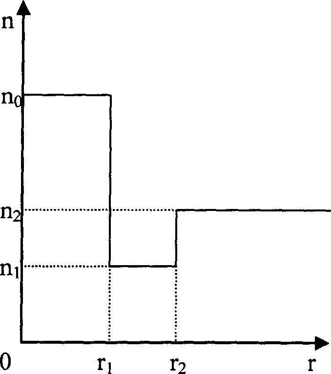
The invention relates to a micro optical fiber, especially providing a micro optical fiber with stop function on long wavelength, which can be used in optical fiber laser, optical fiber amplifier, and optical fiber filter. It is formed by core fiber, reflective index concave layer and coat. Wherein, the reflective index concave layer is between the core fiber and the coat; the reflective index concave layer and the coat have some arranged holes, via whose shape, size, and distribution, to control the average effective reflective index, to make the reflective index of concave layer lower than the reflective indexes of core fiber and coat. Compared to common optical fiber, the invention can control reflective index more accurately and easily, while it has large long wavelength loss and small short wavelength loss, to be used as optical filter. The core filter is doped with rare earth ion; the low reflective index layer can make the light emitted by doped optical fiber excurse to short wavelength, to prepare special optical fiber powered device.

Description

technical field [0001] The invention relates to a microstructure optical fiber, in particular to a microstructure optical fiber with a special structure that has a cut-off function for long waves, and can be used in optical fiber lasers, optical fiber amplifiers, and optical fiber filters. Background technique [0002] The explosive development of the Internet and the emergence of concepts such as digital earth have caused a sharp increase in data traffic, and the expansion of optical fiber communication systems has become a hot research topic. There are many ways to expand capacity, and one of the most direct ways is to expand the communication bandwidth, that is, to extend the communication bandwidth from the commonly used C-band (1530-1565nm) to L-band (1565-1625nm) and S-band (1460-1530nm) Wait. The expansion of communication bandwidth will inevitably lead to the demand for optical devices in corresponding bands, among which fiber light source and fiber amplifier are in...

Claims


Application Information

Patent Timeline
IPC IPC(8): G02B6/02G02B1/04G02B1/02C03B37/012
CPCC03B2203/14C03B37/0122C03B2203/42C03B2201/34C03B2203/22
Inventor 陈胜平吕可诚李乙钢丁镭周寿桓
Owner NANKAI UNIV
Learn More