
Laser phase noise measurer

A noise measurement and laser technology, applied in measurement devices, noise figure or signal-to-noise ratio measurement, measurement electronics, etc., can solve the problems of increased cost of measurement devices, complex and difficult system adjustment, and limited applications, to reduce difficulty and shorten the optical path. , the effect of simplifying the operation

Inactive Publication Date: 2010-05-12
SHANXI UNIV
View PDF2 Cites 0 Cited by
  • Summary
  • Abstract
  • Description
  • Claims
  • Application Information

AI Technical Summary

Problems solved by technology

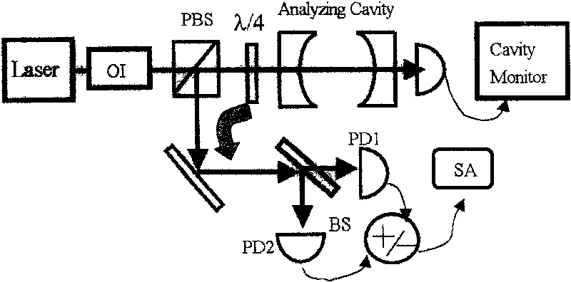
However, because the fineness of the F-P interferometer is very high, it is time-consuming and laborious to adjust; and it requires high environmental conditions: 1) usually requires precise temperature control, which requires a temperature control system; 2) usually requires thermal expansion coefficient Small and hard materials are used to make the F-P cavity, and a pair of high-reflection mirrors with strict coating requirements are required
These will increase the cost of the measuring device and make the system complex and difficult to adjust, which greatly limits its application

Method used


Image

  • Laser phase noise measurer
  • Laser phase noise measurer
  • Laser phase noise measurer

Examples


Embodiment Construction

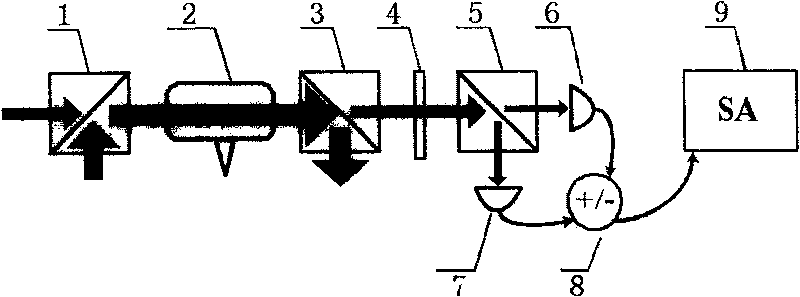
[0020] The phase noise measurement device of the present invention will be further described in detail below in conjunction with the accompanying drawings.

[0021] A phase noise measurement device (such as figure 1 As shown), the phase noise conversion device is composed of the first polarizing beam splitting prism 1, the atomic gas cell 2, and the second polarizing beam splitting prism 3, and the λ / 2 wave plate 4, the third polarizing beam splitting prism 5, the first low The noise detector 6, the second low-noise detector 7 and the adder-subtractor 8 form a balanced zero-beat detection system.

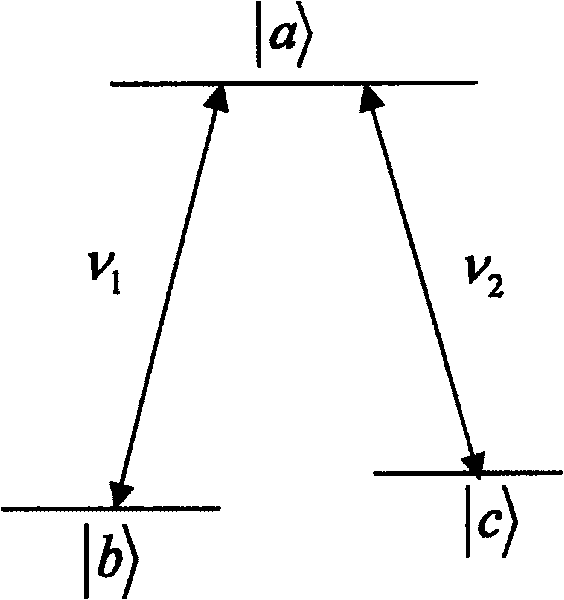
[0022] Let's take cesium atom as an example to make a specific introduction. The linearly polarized light output by the two semiconductor lasers is used as the probe light and coupling light and coupled together through the first polarizing beam splitting prism 1, where the extinction ratio of the first polarizing beam splitting prism is 25dB, thereby ensuring the linear polarizat...


PUM


Abstract

The disclosed testing device for laser phase noise comprises: a phase noise conversion device with two polarization beam-splitting lens (1) and (3), and an atom gas chamber or molecule gas chamber (2). Wherein, coupling two beam linear polarization light by (1) to spread into (2), converting the phase noise into amplitude noise by electromagnetic induced coherence effect, using (3) to divide the detecting light and coupling light, and using a balance zero-beat system to detect the outgoing noise. This invention simplifies device fit to mobile and wide application.

Description

technical field [0001] The invention relates to a measuring device of a laser, in particular to a device for measuring the phase noise of a laser by using the coherent effect of atoms or molecules. technical background [0002] Phase noise is one of the important indicators of lasers. It is an important research object in the fields of basic experiments of quantum optics, quantum measurement and quantum communication. In the gain medium of the laser, the phase of the spontaneously emitted photons is random and disordered, and this process leads to the change of the output field intensity, thereby causing the relaxation oscillation of the resonator. At this frequency, the refractive index of the cavity medium changes, so the linewidth of the output light is broadened. [0003] Some experimental results show that this phase noise is concentrated in the low frequency region (<1MHz), which is mainly caused by the fluctuation of the output laser wavelength. It is found that...

Claims


Application Information

Patent Timeline
Patent Type & Authority Patents(China)
IPC IPC(8): G01R29/26G01R31/00
Inventor 张俊香王海红董雅宾蔡瑾郜江瑞
Owner SHANXI UNIV
Learn More