Normal atmosphere plasma burnishing device

An atmospheric pressure plasma and polishing device technology, applied in the field of polishing devices, can solve the problems of difficult surface cleaning, low efficiency, surface and subsurface damage, etc.

Active Publication Date: 2006-12-13
HARBIN INST OF TECH
View PDF0 Cites 25 Cited by
  • Summary
  • Abstract
  • Description
  • Claims
  • Application Information

AI Technical Summary

Problems solved by technology

[0011] The purpose of the present invention is to solve the shortcomings of the conventional mechanical polishing method in the processing of large light reflectors,

Method used


Image

  • Normal atmosphere plasma burnishing device
  • Normal atmosphere plasma burnishing device
  • Normal atmosphere plasma burnishing device

Examples


specific Embodiment approach 1

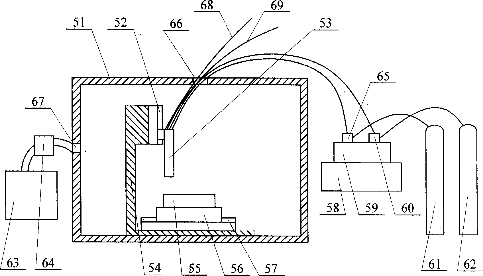
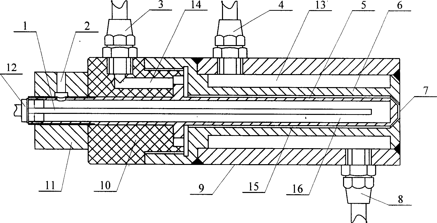
[0013] Specific implementation mode one: (see figure 1 , figure 2 ) This embodiment consists of a closed working cabin 51, a first linkage system 52, a plasma torch 53, a workbench 56, a second linkage system 57, a radio frequency power supply 58, a radio frequency matching device 59, a first flow controller 60, and a reaction gas bottle 61. Composed of plasma gas bottle 62, gas recovery treatment device 63, negative pressure pump 64, second flow controller 65, water inlet pipe 68 and water outlet pipe 69, the first linkage system 52 and the second linkage system 57 are fixed together at the On the common base 54 on the bottom inner wall of the airtight working cabin 51, the plasma torch 53 is installed on the first linkage system 52 and can realize linear motion and rotary motion on the first linkage system 52. The first linkage system 52 mainly functions In order to adjust the distance between the plasma torch 53 and the workpiece 55 and ensure that the axis direction of t...

specific Embodiment approach 2

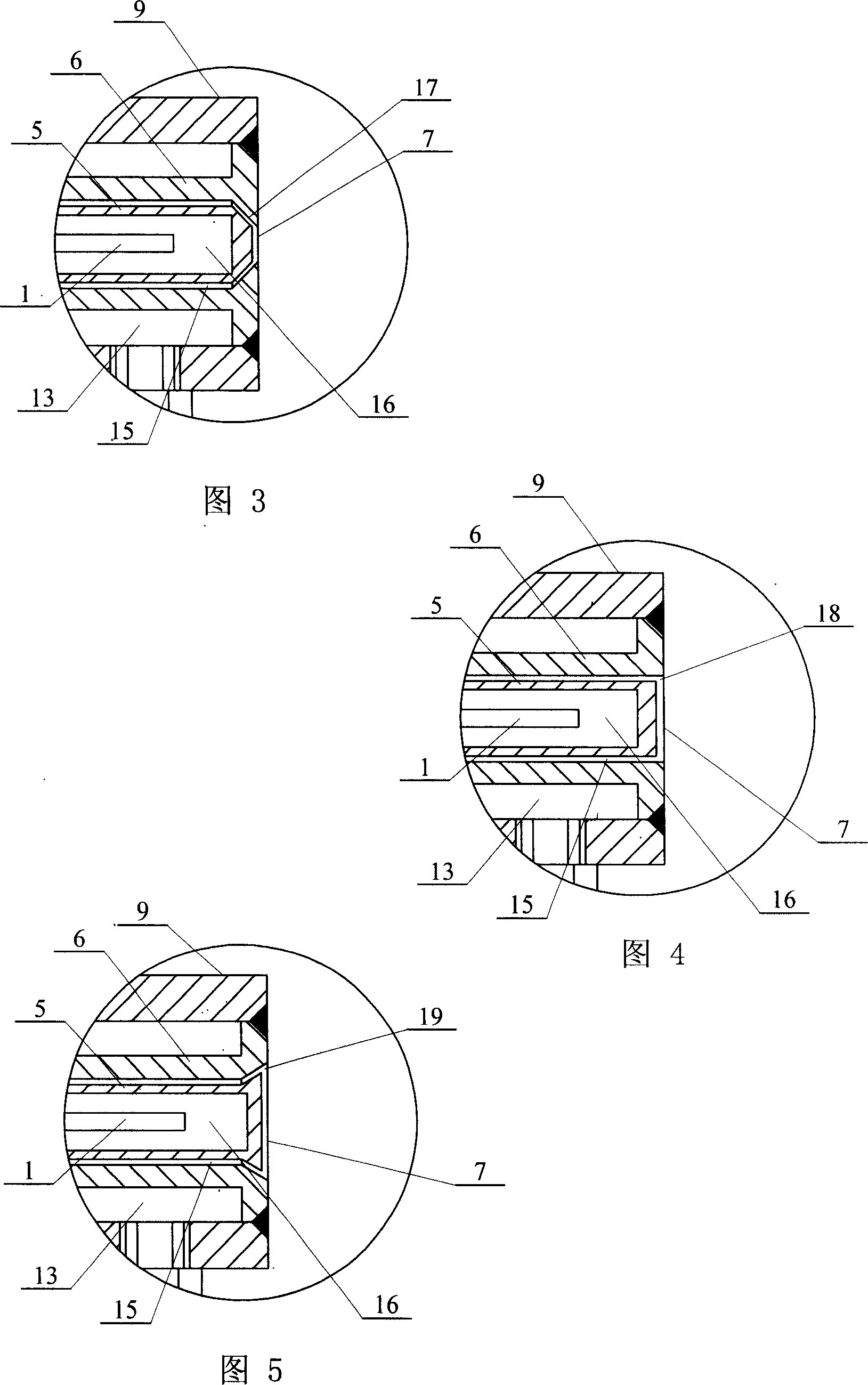
[0015] Specific implementation mode two: (see figure 2 , Fig. 3) The outlet 7 of the cathode 6 of the plasma torch 53 of the present embodiment is a small truncated cone shape 17 with a large inner opening and a small outer opening, and the right end of the anode 5 corresponds to the truncated cone shape 17 of the outlet 7 of the cathode 6. Other compositions and connections are the same as in the first embodiment.

specific Embodiment approach 3

[0016] Specific embodiment three: (referring to Fig. 4) the outlet 7 of the cathode 6 of the plasma torch 53 of the present embodiment is a straight mouth shape 18, and the right end of the anode 5 corresponds to the straight mouth shape 18 of the outlet 7 of the cathode 6. Other compositions and connections are the same as in the first embodiment.


PUM


Abstract

The invention relates to an atmospheric plasma buffing attachment. The invention aims to overcome shortcomings in normal mechanical buffing process and solve problems of low efficiency, damage for surface and semi-surface and hardness for clean in process of preparing ultra-smooth surface with fragile material such as silicon carbide. The main components comprise: sealed working capsule (51), plasma torch (53), the first linked system (52), the second linked system (57), the first flow quantity controller (60), the second flow quantity controller (65), reacting gas bottle (61), plasma gas bottle (62), and gas recycle treating device (63); the plasma torch is installed on the first linked system. The ultra-smooth surface is realized under normal pressure through plasma chemical reaction, which can reduce device cost and enlarge application range. The working efficiency is ten times than that of traditional method, and there is no surface damage and no surface pollution.

Description

technical field [0001] The invention relates to a polishing device. Background technique [0002] The development of modern short-wave optics, strong light optics, electronics and thin film science has very strict requirements on the surface, and its obvious characteristic is that the surface roughness is less than 1nm Ra. When this type of surface is used as an optical element, in order to obtain the highest reflectivity, special emphasis is placed on low surface scattering characteristics or extremely low roughness values; when used as a functional element, because most of them are crystal materials, more attention is paid to the surface roughness. Lattice integrity of the surface. We collectively refer to these two types of surfaces as ultra smooth surfaces. The root mean square value of microscopic undulations on ultra-smooth surfaces is several atoms in size, so the key to realizing ultra-smooth surface processing is to realize the removal of surface materials at the ...

Claims


Application Information

Patent Timeline
IPC IPC(8): B24B1/00
Inventor 王波张巨帆王浪平张龙江董申
Owner HARBIN INST OF TECH
Why Eureka
Try Eureka