Methanol catalytically reforming hydrogen producing apparatus utilizing afterheat of internal combustion engine and its control method

A technology for catalytic reforming and hydrogen production devices, applied in chemical instruments and methods, inorganic chemistry, hydrogen and other directions, can solve the problems of low methanol conversion rate, low hydrogen production rate, limited catalyst coating area, etc., and achieve methanol conversion rate. The effect of high and high hydrogen production rate

Inactive Publication Date: 2007-01-03
BEIJING UNIV OF TECH
View PDF1 Cites 25 Cited by
  • Summary
  • Abstract
  • Description
  • Claims
  • Application Information

AI Technical Summary

Problems solved by technology

Steel pipe methanol reformer (Chinese patent CN85109487B inventor: Dong Yintan Zhao Weizhi) is welded to 2 end plates by 10 to 20 thin-walled stainless steel tubes. The reforming catalyst is coated on the outside to catalyze methanol and water vapor. Due to the small outer surface area of ​​the steel pipe and the limited catalyst coating area, it is difficult for methanol and water vapor in the cavity of the reformer to undergo reforming reactions without contact with the catalyst. , leading to low hydrogen production rate and low methanol conversion rate
Plate-fin methanol reformer (Pan Liwei, Wang Shudong, hydrogen production by steam reforming of methanol in a plate-fin reactor, Acta Chemina Sinica, 2005, 56(3): 468-473) is welded by corrugated stainless steel sheets and shrouds As many waves as possible are used to increase the surface area of ​​catalyst coating and heat exchange. The reformer is divided into inner chamber-combustion gas chamber and outer chamber-methanol and water vapor reaction chamber. Coating the catalyst makes it difficult for the methanol and water vapor in the reaction chamber away from the surface of the corrugated plate to undergo a reforming reaction, and is directly discharged from the exhaust port, resulting in low hydrogen production rate and low methanol conversion rate

Method used


Image

  • Methanol catalytically reforming hydrogen producing apparatus utilizing afterheat of internal combustion engine and its control method
  • Methanol catalytically reforming hydrogen producing apparatus utilizing afterheat of internal combustion engine and its control method

Examples


Embodiment Construction

[0022] Specific implementation examples

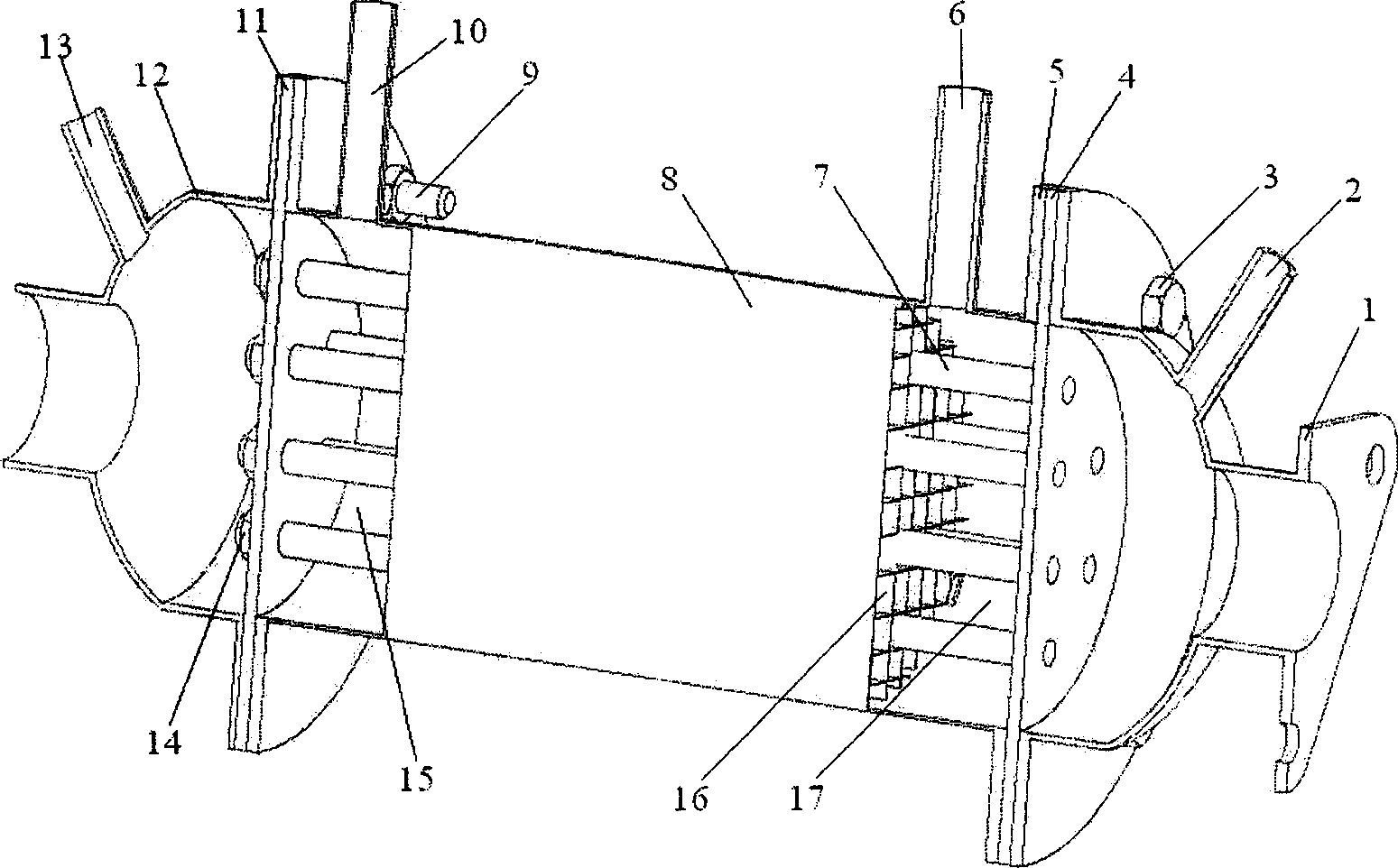
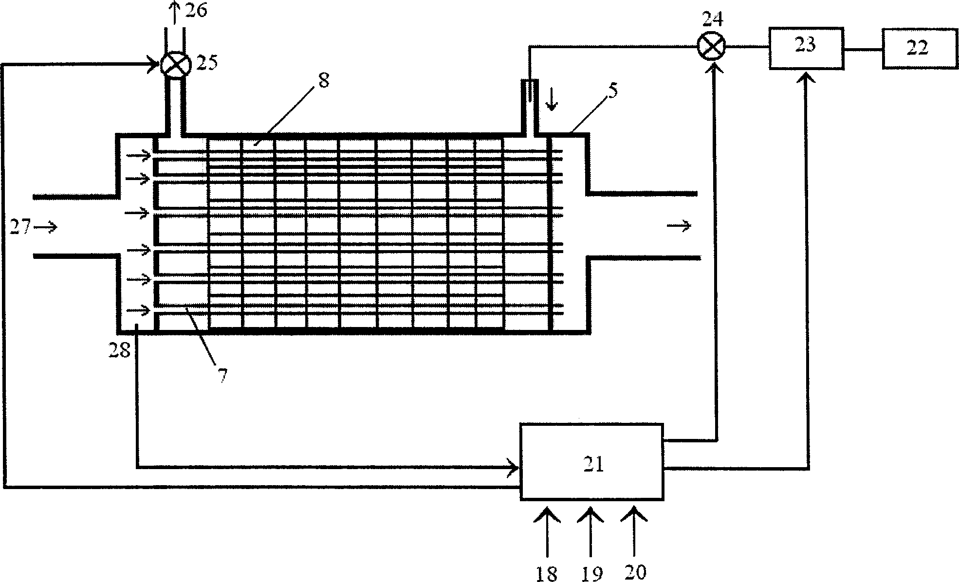
[0023] Combine below figure 1 , figure 2 Specific examples of the present invention will be described. The front end cover 1 of the reformer is connected to the reformer shell 5 through the front fastening screw 3 , and the front end plate 4 of the heat exchanger is arranged between the front end cover 1 and the reformer shell 5 . The reformer housing 5 is connected with the rear end plate 11 of the heat exchanger and the rear end cover 12 of the reformer through rear fastening screws 9 . The heat exchange tube 7 passes through the porous honeycomb ceramic 8 , one end of the heat exchange tube 7 is welded to the front end plate 4 of the heat exchanger, and the other end is fastened and sealed with the rear end plate 11 of the heat exchanger by a fastening nut 14 . The methanol aqueous solution enters the methanol aqueous solution gasification chamber 17 through the methanol aqueous solution inlet 6 on the reformer shell 5, and is v...


PUM


Abstract

The present invention relates to internal combustion engine afterheat utilizing technology, and is especially methanol catalytically reforming hydrogen producing apparatus utilizing afterheat of internal combustion engine and its control method. The apparatus includes mainly methanol aqua gasifying cavities in the front part, middle part and back part of the reformer casing, catalytically reacting cavity and reformed gas product cavity. In the middle part inside the reformer casing, there are porous honeycomb ceramic with inside catalytically reacting cavity; and the inner wall of the catalytically reacting cavity has set honeycomb pores with reforming catalyst coated to the inner wall. One heat exchange pipe penetrates the porous honeycomb ceramic axially. The present invention has integrated heat exchange pipe and porous honeycomb ceramic, and possesses compact structure, high heat exchange efficiency, high hydrogen rate and other advantages.

Description

technical field [0001] The invention relates to a methanol catalytic reforming hydrogen production device utilizing waste heat of an internal combustion engine and a control method, belonging to the field of waste heat application of an internal combustion engine. Background technique [0002] Environmental protection and transformation of energy structure are the two major themes of the 21st century. Hydrogen fuel, with its unique advantages in energy and environmental protection, is expected to promote the arrival of an economic era marked by it. Hydrogen energy is regarded as the energy source with the greatest potential for development in this century because of its cleanliness, high efficiency, and renewability, and the existing petroleum fuel-burning automobile internal combustion engines can burn hydrogen with a slight modification. In addition, hydrogen fuel also has many advantages when used in automobiles. For example, the calorific value per unit mass of hydrogen ...

Claims


Application Information

Patent Timeline
Patent Type & Authority Applications(China)
IPC IPC(8): C01B3/32
Inventor 纪常伟何洪
Owner BEIJING UNIV OF TECH
Why Eureka
Try Eureka