Motor vehicle exhaust catalytic converter, and its preparing method

A technology for catalytic converters and motor vehicles, used in exhaust devices, mechanical equipment, machines/engines, etc., can solve the problems of reduced catalytic activity, high cost, unsuitable coating, etc., to improve the purification effect and prolong the service life , combined with a strong effect

Inactive Publication Date: 2007-01-10
韩昭
0 Cites 7 Cited by

AI-Extracted Technical Summary

Problems solved by technology

However, the high-temperature oxidation process is to form an alumina whisker transition layer on the surface of FeCrAl metal, which is only suitable for metal supports rich in aluminum. This process cannot be used for ordinary metal supports, and its industrial application is limited; after surface phosphating process Phosphorus on the surface of the metal carrier can easily lead to phosphorus poisoning of the catalyst, forming a glassy compound on the surface of the catalyst, causing the loss of active points, reducing the catalytic activity, causing the catalytic converter to lose part or all of its functions too quickly, and significantly ...

Abstract

The invention discloses a motor vehicle exhaust catalytic converter, where the catalyst carrier is a metal cellular carrier using hot dip aluminized thin steel plate as precursor and made by micro-arc oxidized ceramic film process; the carried catalyst coating is a noble metal-rare earth combined catalyst coating formed on the carrier by making YSZ and Pd into mixed pulp and coating it on the carrier. And the invention also discloses a method for preparing the motor vehicle exhaust catalytic converter, making hot dip plating aluminum by salt bath process and in situ growing the ceramic film on the surface of the hot dip aluminized thin steel plate by micro-arc oxidizing process, where the ceramic film has a structure of crystalline oxide ceramic phase, compact and even, firm to bond, and having low making energy consumption, and outstanding advantages of improving purifying effect and prolonging the service life. And it is applied to exhaust purification for various motor vehicles using leadless gasoline.

Application Domain

Technology Topic

Image

  • Motor vehicle exhaust catalytic converter, and its preparing method

Examples

  • Experimental program(1)

Example Embodiment

[0046] A motorcycle exhaust catalytic converter
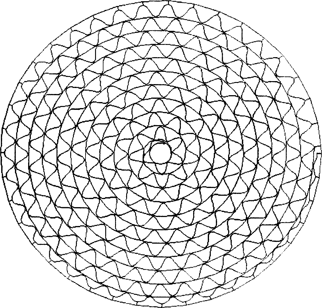
[0047] The motorcycle exhaust catalytic converter includes a carrier shell, a catalyst carrier placed in the carrier shell, and a leading fluid and a rear leading fluid respectively placed before and after the catalyst carrier. The catalyst carrier is composed of a flat substrate and a A concentric coiled metal honeycomb carrier in which wavy wave carrier plates are wound with each other, and the accompanying drawing is a schematic diagram of its sectional structure.
[0048] The catalyst carrier is a concentrically wound metal honeycomb carrier made of a hot-dip aluminized steel sheet as a precursor by a micro-arc oxidation ceramic film process, which meets the general technical conditions for motorcycle catalytic converters stipulated by national industry standards.
[0049] The catalyst coating carried on the catalyst carrier is a composite catalyst coating of precious metal and rare earth, which is made of rare earth oxide Y. 2 O 3 Yttrium Stabilized Zirconia ZrO as Additive 2 (YSZ) and palladium (Pd) are made into a mixed slurry to coat the coating formed on the catalyst carrier.
[0050] The content ratio of YSZ and Pd in ​​the mixed slurry of YSZ and Pd is (900-1000):1.
[0051] The thin steel plate is a carbon steel thin plate with a steel grade of A3.
[0052] The preparation method of the motorcycle exhaust gas catalytic converter comprises the following steps: making a metal honeycomb carrier by a back-rolling method, and applying an active coating. step, before the step of applying the active coating, there are successively the steps of hot dip aluminum plating and micro-arc oxidation, and then the honeycomb carrier is rolled and then tightly fixed. The specific steps are in order of sheet shearing, stamping, hot-dip aluminizing, degreasing, water washing, micro-arc oxidation, re-washing, drying, applying active coating, baking, rolling honeycomb carrier and rivet fixing.
[0053] The hot-dip aluminizing is to prepare a hot-dip aluminized steel sheet by a salt bath method, which is heated by a SG-3-12 type high temperature crucible resistance furnace, and a KSY type thyristor temperature controller is used to control the furnace temperature. The melting aluminum crucible is a high temperature. For ceramic crucibles, a flat sheet steel with a clean surface of steel grade A3 or a rolled honeycomb sheet is immersed in liquid aluminum with a melting temperature of 730°C for 3 minutes, and a series of physical and After the chemical reaction is proposed, it is cooled to room temperature in the air. After cleaning the residual salt on the surface of the aluminized film, an aluminum layer is formed on the surface of the thin steel plate, which is the product. The thickness of the aluminized film is 20um. Micrometer measurement. The liquid aluminum is industrial pure aluminum with a purity greater than 99.7wt%, and the plating aid is NaCl+Na 3 AlF 6.
[0054] The micro-arc oxidation is to use a micro-arc oxidation process to grow a ceramic film on the surface of a hot-dip aluminized steel sheet in situ, and a three-phase semi-controlled bridge rectifier power supply with continuously adjustable voltage is used, and the voltage is 400V-700V. The electrolytic cell is made of stainless steel, which is placed in a cooling water tank to control the temperature of the electrolyte. The anode in the electrolytic cell is a hot-dip aluminized steel plate, and the cathode is a stainless steel electrolytic cell. During the micro-arc oxidation process, stepless speed regulation is used for stirring. The device stirs the electrolyte solution to make the composition of the electrolyte solution uniform. The hot-dip aluminized steel sheet is placed in an electrolytic cell with temperature control and stirring functions, and the DC power supply is turned on to make the aluminum metal on the surface of the hot-dip aluminized steel The electrolyte solution interacts to form a micro-arc discharge in-situ growth ceramic film on the surface. The electrolyte solution is a mixture of sodium silicate and sodium hydroxide with a content ratio of 40:1. The temperature of the electrolyte solution is 20°C and the current density is 0.010A. /cm 2 ~0.10A/cm 2.
[0055] The coating of the active coating is to make YSZ and Pd into a coating containing a catalyst, coat the coating on the catalyst carrier, and bake at a temperature of 700 DEG C to form the active coating.
[0056] The preparation of described YSZ has the following steps successively:
[0057] 1) Weigh Y (NO 3 ) 3 ·6H 2 O and Zr (NO 3 ) 4 ·5H 2 O, take ammonia water as the complexing agent, mix well, heat the temperature to 60°C, and stir the mixture for 20min;
[0058] 2) Ammonia water was added at a speed of 40 drops/min to promote the formation of brownish-yellow gel precipitation, the pH value was adjusted to 10, and the mixture was stirred for 60min and then sealed;
[0059] 3) filter the resulting precipitate, repeatedly wash the precipitate with water, and wash away ammonia and nitrate;
[0060] 4) heating temperature to 130 ℃ drying;
[0061] 5) Pre-sintering at 330°C for 1.5h, and then calcining at 720°C for 4h;
[0062] 6) After cooling, take out the product yttrium-stabilized zirconia Y 0.5 Zr 0.5 O 2 powder.
[0063] The current density of this embodiment drops to 100A/m 2 time, per m 2 The manufacturing cost of carbon steel micro-arc oxidation ceramic film is less than RMB 20, and the carbon steel hot-dip aluminized micro-arc oxidation ceramic film honeycomb carrier of φ35×100 is priced at less than RMB 6 per piece, while the FeCrAl metal of the same type and specification is priced below RMB 6. Each carrier is priced at RMB 15-17. The samples tested by the National Motorcycle Quality Supervision and Inspection Center have reached the European No. 3 emission standard, and the conversion rate used for four-stroke motorcycles meets: HC≥75%, CO≥80%, NOx≥30%, HC, CO , NOx and particulate matter emission concentrations meet the requirements of GB 14621. After installing the catalytic converter, the power performance of the vehicle will not decrease by more than 5%. Compared with the original vehicle, the fixed noise of the vehicle will not exceed the noise level of the original vehicle, and the endurance test mileage will reach 10%. thousand kilometers.
[0064] The above content is a further detailed description of the present invention in conjunction with specific preferred embodiments, and it cannot be considered that the specific implementation of the present invention is limited to these descriptions. For those of ordinary skill in the technical field of the present invention, without departing from the concept of the present invention, some simple deductions or substitutions can be made, all of which should be regarded as belonging to the patent of the present invention determined by the submitted claims. protected range.

PUM

PropertyMeasurementUnit
Current density0.01 ~ 0.1A/cm²
Thickness10.0 ~ 30.0µm
tensileMPa
Particle sizePa
strength10

Description & Claims & Application Information

We can also present the details of the Description, Claims and Application information to help users get a comprehensive understanding of the technical details of the patent, such as background art, summary of invention, brief description of drawings, description of embodiments, and other original content. On the other hand, users can also determine the specific scope of protection of the technology through the list of claims; as well as understand the changes in the life cycle of the technology with the presentation of the patent timeline. Login to view more.

Similar technology patents

Classification and recommendation of technical efficacy words

  • Low cost
  • Strong combination

Semiconductor device

InactiveUS6975142B2Low costReduce manufacturing stepsTransistorSolid-state devicesVoltage amplitudeSemiconductor
Owner:SEMICON ENERGY LAB CO LTD

Method for processing high-temperature alloy furnace tube

ActiveCN101565807AStrong combinationMitigation of catalytic cokingSolid state diffusion coatingProduct gasMetallurgy
Owner:CHINA UNIV OF PETROLEUM (BEIJING)

Preparation method of macroporous aluminum oxide with diplopore distribution

InactiveCN101214454AStrong combinationOvercoming low mechanical strengthCatalyst carriersCarbon blackPetroleum
Owner:SHANGHAI SECOND POLYTECHNIC UNIVERSITY
Why Eureka
Try Eureka