
Laser synthetic method for negative expansion coefficient material

A technology of negative thermal expansion coefficient and laser synthesis, which is applied in the field of laser application technology and material synthesis, can solve problems such as chemical ratio mismatch, achieve fast speed, avoid decomposition, and save the effect of waste liquid treatment

Inactive Publication Date: 2007-04-11
ZHENGZHOU UNIV
View PDF0 Cites 6 Cited by
  • Summary
  • Abstract
  • Description
  • Claims
  • Application Information

AI Technical Summary

Problems solved by technology

The disadvantages of this method are: ① Since ZrW 2 o 8 The stable phase has a very narrow temperature range of 1150-1257°C, which determines that its sintering needs to be carried out at a corresponding high temperature, and the preparation process generally takes 3-5 days to complete; ②ZrW 2 o 8 Decomposes into ZrO at 770-1050°C 2 and WO 3 , so it is usually cooled in liquid nitrogen immediately after being released from the furnace to reduce decomposition during cooling; ③WO 3 A large amount of volatilization during long-term sintering will cause chemical ratio mismatch

Method used


Image

  • Laser synthetic method for negative expansion coefficient material
  • Laser synthetic method for negative expansion coefficient material
  • Laser synthetic method for negative expansion coefficient material

Examples


Embodiment 1

[0036] Embodiment 1, laser synthesis negative thermal expansion coefficient material ZrW 2 o 8 :

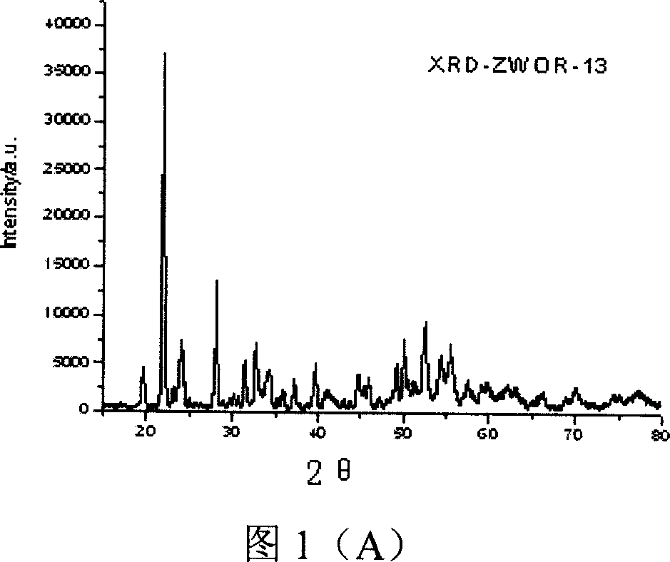
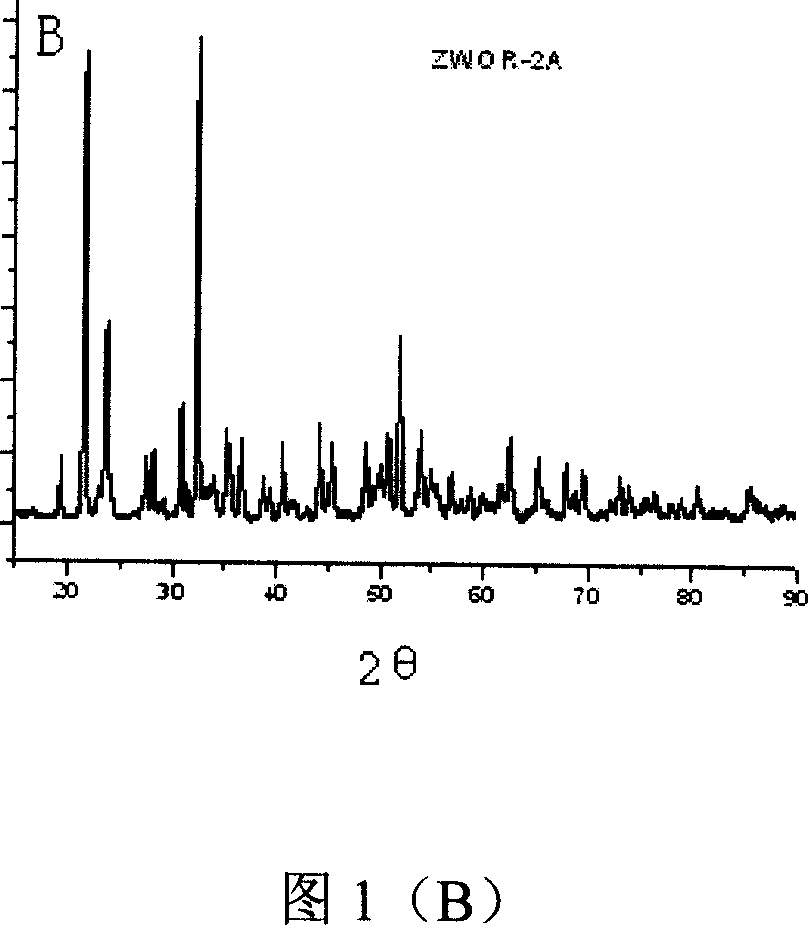
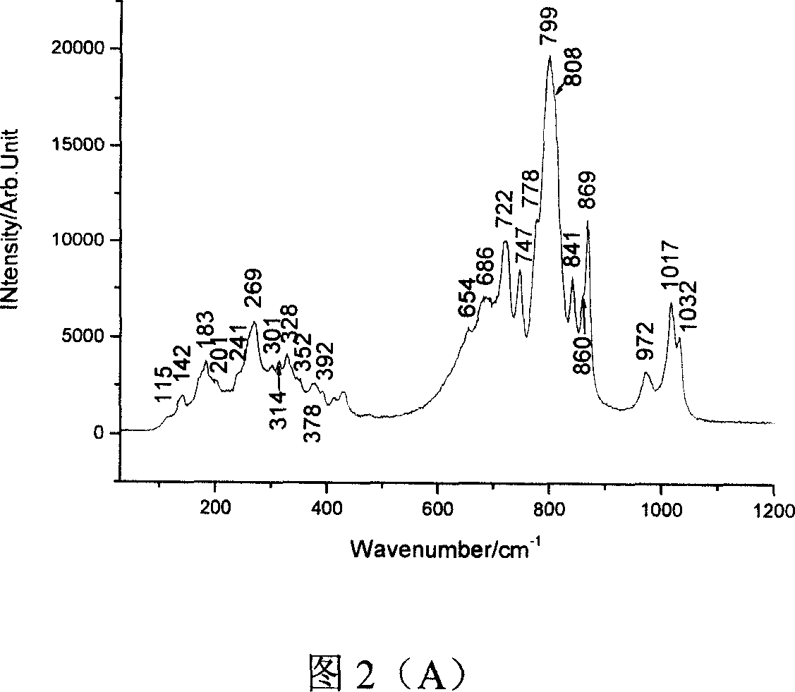
[0037] Weigh ZrO at a molar ratio of 1:2 2 with WO 3 , mixed and ground for 90 minutes, the mixture was compacted, and then laser synthesized. Laser synthesis process parameters are: laser wavelength 10.6μm, power density 1.03kW / cm 2 , beam scanning speed 6mm / s. The laser-synthesized material is a uniform green block, and the macroscopic appearance is flat and smooth. The corresponding X-ray diffraction and Raman spectra are shown in Figure 1 (A), (B), and Figure 2 (A), (B), (C).

[0038] XRD analysis by and 、 , "Search-Match" and other XRD database comparisons are completed (the same below). X-ray Diffraction Phase Analysis Shows Laser Synthesized ZrW 2 o 8 Mainly γ phase (Figure 1A), and the γ phase ZrW with space group P212121 and ICSD card number 56566 2 o 8 The XRD matches perfectly. After annealing at 200 °C, ZrW 2 o 8 From γ phase to α phase, and the ...

Embodiment 2

[0041] Example 2: Laser synthesis of negative thermal expansion coefficient material ZrW 2 o 8 :

[0042] Weigh ZrO at a molar ratio of 1:2 2 with WO 3 , mixed and ground for 90 minutes, the mixture was compacted, and then laser synthesized. Laser synthesis process parameters are: laser wavelength 10.6μm, power density 0.2kW / cm 2 , beam scanning speed 0.2mm / s. The laser-synthesized material is a uniform green block, and the macroscopic appearance is flat and smooth. The corresponding Raman spectrum is shown in Figure 2(B).

Embodiment 3

[0043] Embodiment 3: Laser synthesis of negative thermal expansion coefficient material ZrW 2 o 8 :

[0044] Weigh ZrO at a molar ratio of 1:2 2 with WO 3 , mixed and ground for 90 minutes, the mixture was compacted, and then laser synthesized. Laser synthesis process parameters are: laser wavelength 10.6μm, power density 1.5kW / cm 2 , beam scanning speed 12mm / s. The laser-synthesized material is a uniform green block, and the macroscopic appearance is flat and smooth. The corresponding X-ray diffraction and Raman spectra are shown in Figure 2(C).


PUM


Abstract

The laser synthesis process of negative thermal expansion coefficient material belongs to the field of laser technology application. Under the direct heating of laser beam, the raw materials for the negative thermal expansion coefficient material are reacted in a laser bath and solidified fast. The laser is CO2 gas laser or Nd:YAG solid laser of laser wavelength 10.6 micron or 1.06 micron, power density of 0.2-1.5 kW / sq cm and laser scanning speed of 0.2-12 mm / s. The negative thermal expansion coefficient material is ZrW2O8, HfW2O8, Zr1-xHfxW2O8 with x in 0-1.0, Zr1-xHfxMo2O8 with x in 0-1.0, ZrMo2-xWxO8 with x in 0-2.0 or HfMo2-xWxO8 with x in 0-2.0. The present invention has the features of fast synthesis speed, low cost, no pollution and being suitable for continuous production.

Description

technical field [0001] The invention belongs to the field of laser application technology and material synthesis technology, and in particular relates to a laser synthesis method of a negative thermal expansion coefficient material. Background technique [0002] Laser synthesis material technology uses a high-energy-density laser beam as a heat source, and the raw material components react under the action of the laser (or in the laser molten pool) to form new materials and solidify rapidly. Most materials have the property of thermal expansion and contraction, and the thermal stress (or thermal shock wave) generated by thermal expansion and contraction is often the main reason for device fatigue, performance degradation, failure or even fracture and shedding. In the field of aerospace, both functional and structural materials are faced with the severe test of thermal stress (or thermal shock wave). When a spacecraft is in space, it is irradiated by the sun, and the temperat...

Claims


Application Information

Patent Timeline
IPC IPC(8): C04B35/64C04B35/495
Inventor 梁二军王东升晁明举袁斌阮宜斌吴天安
Owner ZHENGZHOU UNIV
Learn More