Method for measuring reflectance ratio of high reflected mirror

A measurement method and technology of reflectivity, which is applied in the field of measurement of high mirror reflectivity, can solve the problems of limited measurement accuracy, signal-to-noise ratio decrease, measurement accuracy limitation, etc., and achieve simplified measurement device, large signal amplitude and simple device Effect

Inactive Publication Date: 2007-05-16
INST OF OPTICS & ELECTRONICS - CHINESE ACAD OF SCI
View PDF2 Cites 49 Cited by
  • Summary
  • Abstract
  • Description
  • Claims
  • Application Information

AI Technical Summary

Problems solved by technology

The disadvantages of this method are: due to factors such as poor quality of pulsed laser beams and mode competition in the ring-down cavity, the measurement accuracy is limited; moreover, due to the high cost of the pulsed laser system used, it is not conducive to popularization and use
When the reflectivity of the cavity mirror is increased to a certain level, the output signal amplitude of the optical cavity is small, and the signal-to-noise ratio decreases, which makes it difficult to adjust the device and limits the measurement accuracy

Method used


Image

  • Method for measuring reflectance ratio of high reflected mirror

Examples


Embodiment Construction

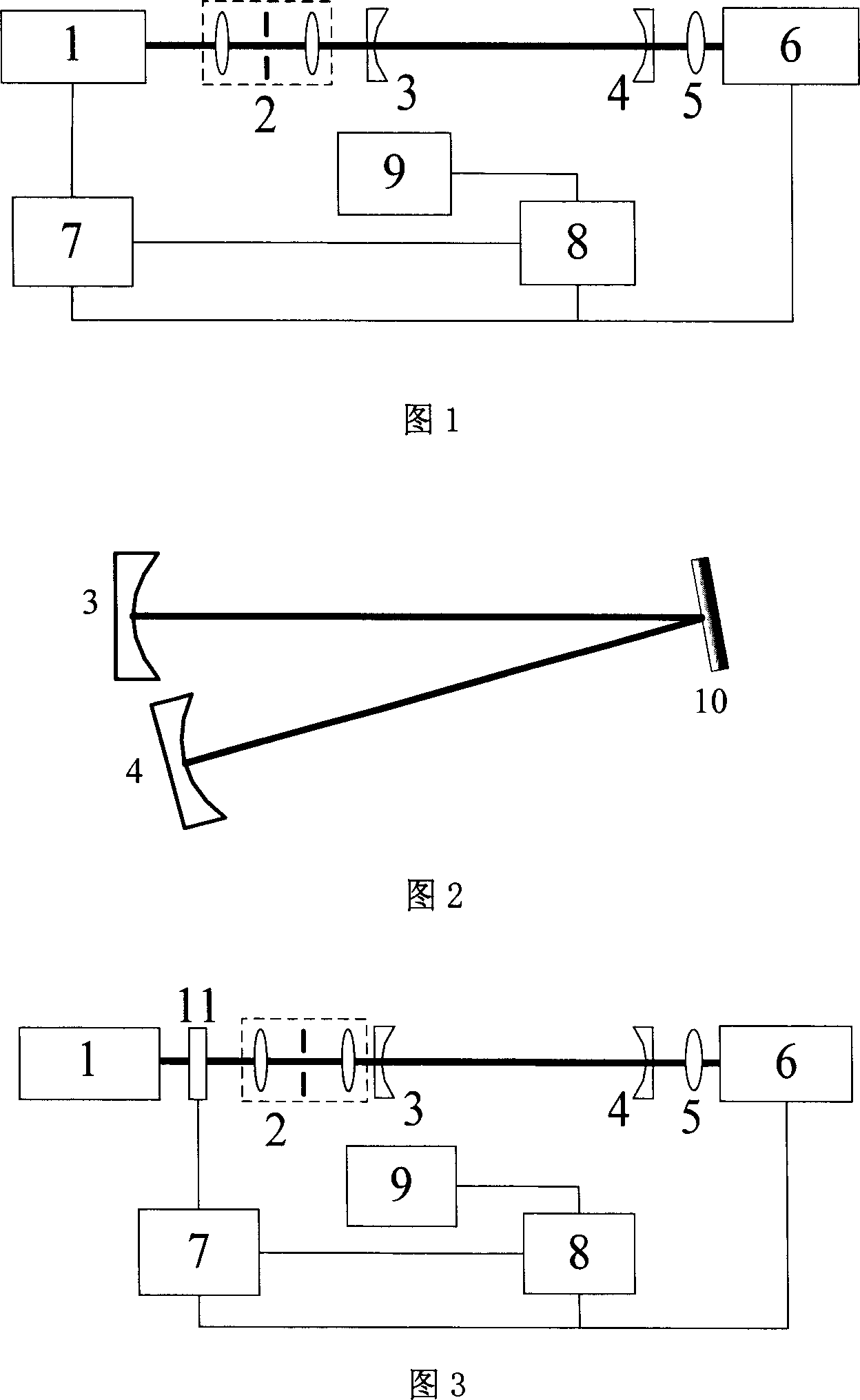
[0025] As shown in Figure 1, measuring device of the present invention is made of light source 1, spatial filtering and telescopic system 2, plano-concave high reflection mirror 3,4, converging lens 5, detector 6, trigger switch circuit 7, oscilloscope 8 and computer 9 composition. The thick line in the figure indicates the optical path, and the thin line indicates the connection of the signal line. Wherein the detector 6 generally adopts a photodiode detector.

[0026] The light source 1 adopts a wide-spectrum continuous semiconductor laser, and its spectral width is between 0.001nm and 50nm, so that the laser spectrum covers multiple optical cavity eigenmodes. The spatial filtering and telescopic system 2 consists of two lenses and a pinhole, and is used to shape the laser beam output by the light source 1 into a fundamental mode and match it with the optical cavity mode. Two identical flat-concave high-reflection mirrors 3 and 4 are coated with a high-reflection film on t...


PUM

PropertyMeasurementUnit
angle of incidenceaaaaaaaaaa

Abstract

This invention discloses one high reflection rate lens measurement method, which comprises the following steps: a, two same concaved high reflected concaved surface form direct chamber and to send continuous laser into stable resonance chamber or co focus chamber and when light chamber output signal range value is larger then set valve value, it closes laser beam to get direct chamber annealing time by index annealing signal matching to get chamber reflection rate; b, keeping chamber length unchanged and adding high reflection lens to form fold chamber between two blocks and when the output signal range value is larger than valve value, it closes laser beam to get fold chamber annealing time to compute test lens reflection rate.

Description

technical field [0001] The invention relates to a method for measuring the parameters of an optical element, in particular to a method for measuring the reflectivity of a high mirror. Background technique [0002] The wide use of high reflectivity optical components in laser systems urgently requires accurate measurement of high reflectivity, and traditional methods can no longer meet the measurement accuracy requirements of high reflectivity. Chinese Patent Application No. 98114152.8, Publication No. CN1242516A, the patent of invention published on January 26, 2000 discloses "a method for measuring the high reflectivity of mirrors". The optical resonant cavity composed of mirrors receives the exponential decay signal of the optical cavity, and determines the ring-down time τ of the straight cavity respectively - and folded cavity ring down time τ < , calculate the reflectivity R of the mirror to be tested. The disadvantages of this method are: due to the poor quality of ...

Claims


Application Information

Patent Timeline
Patent Type & Authority Applications(China)
IPC IPC(8): G01M11/02G01N21/55
Inventor 李斌成龚元
Owner INST OF OPTICS & ELECTRONICS - CHINESE ACAD OF SCI
Why Eureka
Try Eureka