Optical current transformer and method for measuring current with the same

A technology of current transformers and photoelectric converters, used in the measurement of current/voltage, voltage/current isolation, instruments, etc., can solve the problems of weak reflected light, poor measurement accuracy and reliability, and poor long-term stability.

Inactive Publication Date: 2007-05-16
李岩松 +1
View PDF1 Cites 28 Cited by
  • Summary
  • Abstract
  • Description
  • Claims
  • Application Information

AI Technical Summary

Problems solved by technology

Its advantage is that there is no magnetic saturation phenomenon, and the whole process including short circuit can be measured. However, its disadvantage is that the long-term stability is not good. As time goes by, the properties of the reflective surface will change, resulting in a change in the refractive index, the reflected light will become weaker and weaker, and the measurement accuracy and reliability will become worse and worse, so this type of device has not been practically used.

Method used


Image

  • Optical current transformer and method for measuring current with the same
  • Optical current transformer and method for measuring current with the same
  • Optical current transformer and method for measuring current with the same

Examples


specific Embodiment approach 1

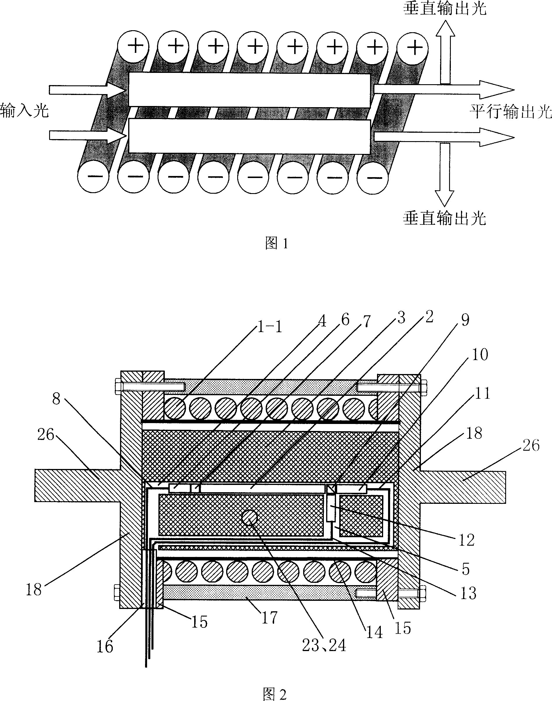
[0089] Specific embodiment one: Fig. 2, Fig. 3 are the optical current transformer schematic diagrams of solenoid type single optical path, an optical sensing head 2, i.e. a straight strip magneto-optical material, one end of which is connected to polarizer 7, Input self-focusing lens 6 and input optical fiber 8, the other end of which is connected to analyzer 9, parallel output self-focusing lens 10 and parallel output optical fiber 11 in sequence, the above-mentioned components are arranged along a straight line, and are connected perpendicularly to the above-mentioned straight line at the analyzer Vertical self-focusing lens 12 and vertical output fiber 13. The centerlines of each element arranged in a straight line are preferably on the same straight line, at least the centerlines of the input self-focusing lens 6 and the parallel output self-focusing lens 10 will be on the same straight line, and the centerlines of the vertical output self-focusing lens 12 are perpendicula...

specific Embodiment approach 2

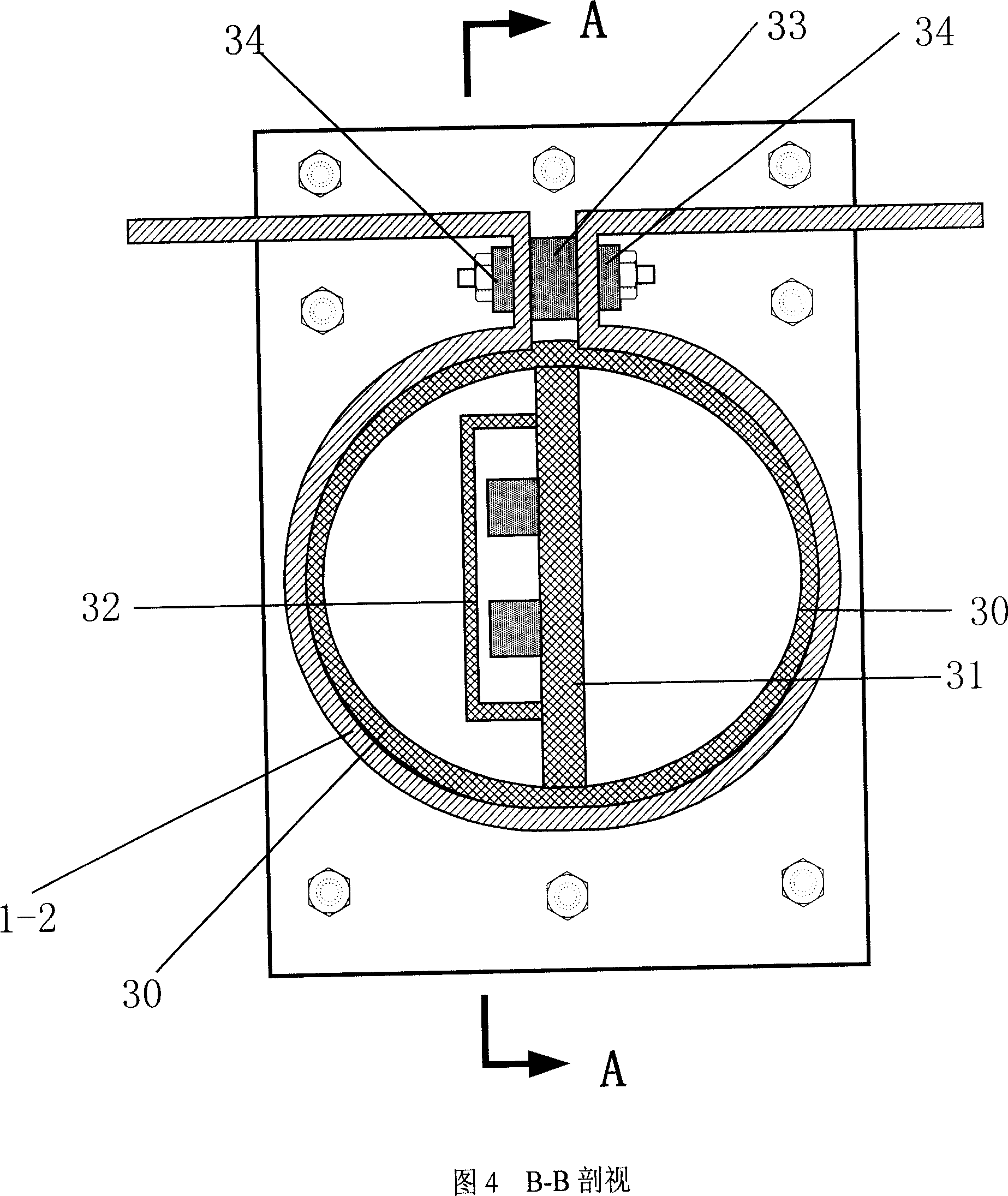
[0096] Embodiment 2: Fig. 4, Fig. 5 and Fig. 6 show schematic diagrams of an Ω hard bus-type optical current transformer with the same two basic optical paths.

[0097] The conductor for the measured current to pass is the Ω-shaped bus bar 1-2 made of wide and flat hard bus bar. The shape of the insulating object is a cylinder 30 on the outside, and a flat plate 31 passing through the busbar is fixed inside the cylinder 30 . The outer diameter of the cylinder 30 is equal to the inner diameter of the cylinder of the Ω-shaped busbar 1-2, and two basic optical paths are arranged symmetrically on one side of the plate 31 (or on both sides respectively). Each basic optical path is an input optical fiber 8, an input self-focusing lens 6, a polarizer 7, an optical sensor head 2, a polarizer 9, a parallel self-focusing lens 10, and a parallel output optical fiber 11 arranged along a straight line. There is also a vertical output self-focusing lens 12 and a vertical output optical fib...

specific Embodiment approach 4

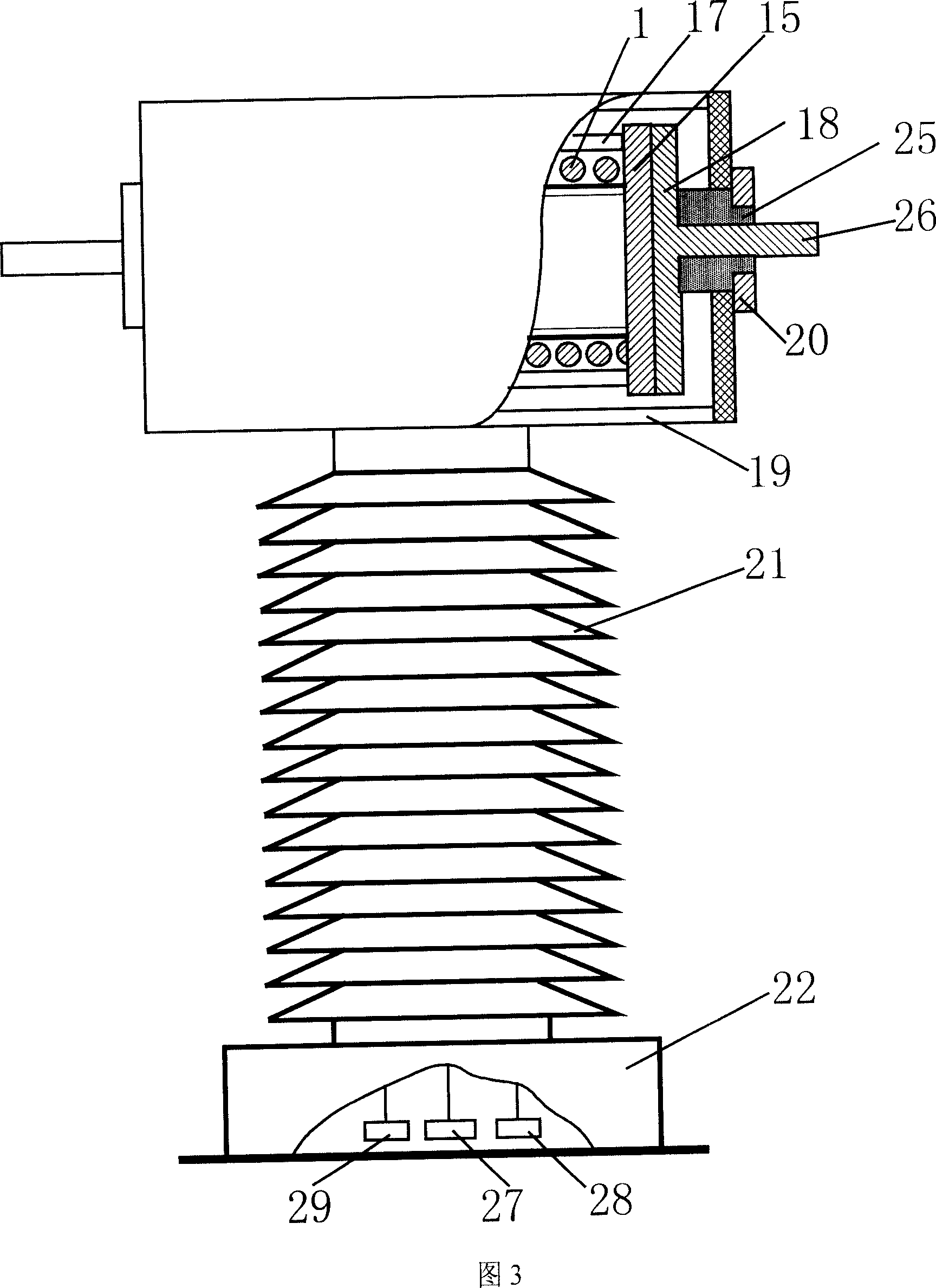
[0106] Embodiment 4: Solenoid type optical current transformer with two identical basic optical paths with high temperature sensitivity and two identical basic optical paths with small temperature sensitivity, see Fig. 2, Fig. 3 and Fig. 7 .

[0107] The conductor for the current to be measured is a solenoid 1-1, and the cylindrical insulating object 3 fixes four basic optical paths in the solenoid, and the said basic optical paths are input optical fibers arranged in sequence along a straight line along the order of light passing. 8. Input self-focusing lens 6, polarizer 7, optical sensing head 2, polarizer 9, parallel output self-focusing lens 10, parallel output optical fiber 11, vertical self-focusing is arranged perpendicular to the above-mentioned straight line at the polarizer 9 Lens 12, vertical output optical fiber 13. The optical sensing head 2 is a straight magneto-optical material, and its two end faces are planes perpendicular to the length direction, and its len...


PUM


Abstract

This invention relates to high voltage circuit current measurement optical inductor and its test method, wherein, the sensor head is of bar magnetic materials along line distribution input fiber; the basic path is composed of self focus lens, bias device, optical sensor head, test bias device, parallel output self focus lens and fiber and vertical output focus lens and fiber. The test current passes through ring conductor to establish parallel magnetic field with at least one basic light path. The multiple light paths each sensor head is of same distance separately connected to low voltage two photoelectricity converters to output voltage signal and vertical voltage to compute test current.

Description

technical field [0001] The invention relates to the improvement of the optical current transformer used in the current measurement and control of the high-voltage line of the power system, in particular to the improvement of the optical current transformer with magneto-optic material as the main sensing device. Background technique [0002] The current transformer is an important equipment for power system measurement and protection control. After long-term development, the accuracy of the electromagnetic current transformer in measuring the steady-state current can reach a few ten thousandths, or even higher; but in the case of a short-circuit fault, the electromagnetic current transformer Severe magnetic saturation occurs in the relay, which leads to the distortion of the secondary output current waveform and cannot describe the transition process of the short-circuit current. This is one of the main reasons for the relay protection to malfunction and refuse to operate. In...

Claims


Application Information

Patent Timeline
Patent Type & Authority Applications(China)
IPC IPC(8): G01R15/18G01R19/00
Inventor 杨以涵郭志忠李岩松于文斌张国庆高桦王贵忠
Owner 李岩松
Why Eureka
Try Eureka