

Process for preparing vanadium oxide film
A technology of vanadium oxide film and sputtering coating, which is applied in ion implantation plating, metal material coating process, coating, etc., can solve difficult problems, achieve excellent performance, reduce process difficulty, and increase repeatability.
- Summary
- Abstract
- Description
- Claims
- Application Information
AI Technical Summary
Problems solved by technology
Method used
Image

Examples
specific Embodiment approach 1
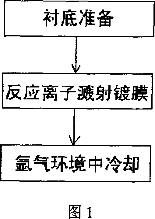
[0019] 1. Using Si-plated 3 N 4 Thin-film Si wafers are used as substrates, and the substrates are cleaned and dried for subsequent use before coating.
[0020] 2. The vanadium oxide film is prepared by reactive ion sputtering coating process, and the specific process conditions are:
[0021] Target material: pure metal vanadium; background vacuum degree: -3 Pa; sputtering temperature: 200±1°C; O 2 : Ar=1:1.6; Working pressure: 2.8±0.6Pa; O during sputtering 2 Flow: 2.4sccm; Ar flow during sputtering: 3.9±0.2sccm; sputtering voltage: 240V;
[0022] Dynamic and precise control of the gas flow during the sputtering process until the end of the coating;
[0023] 3. Naturally cool to room temperature in an argon atmosphere.
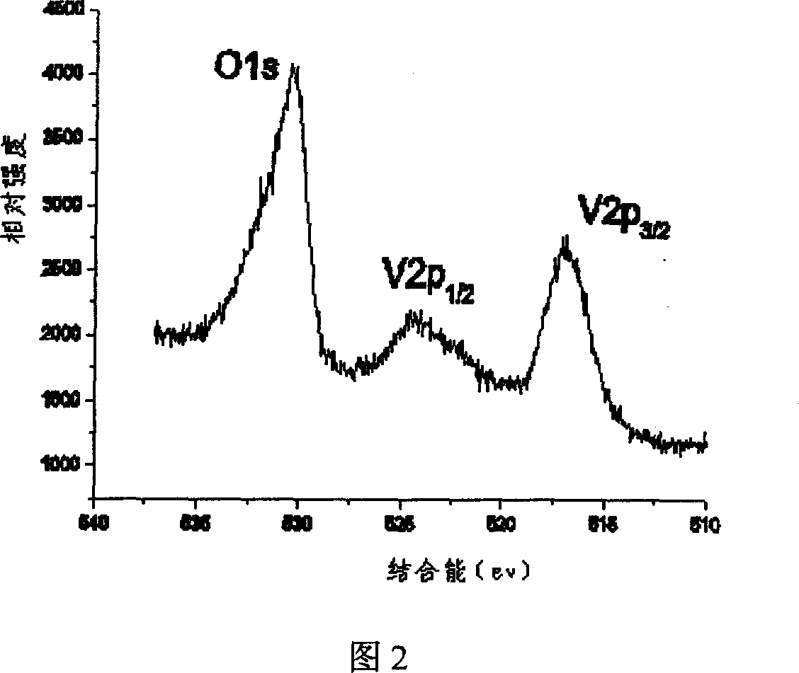
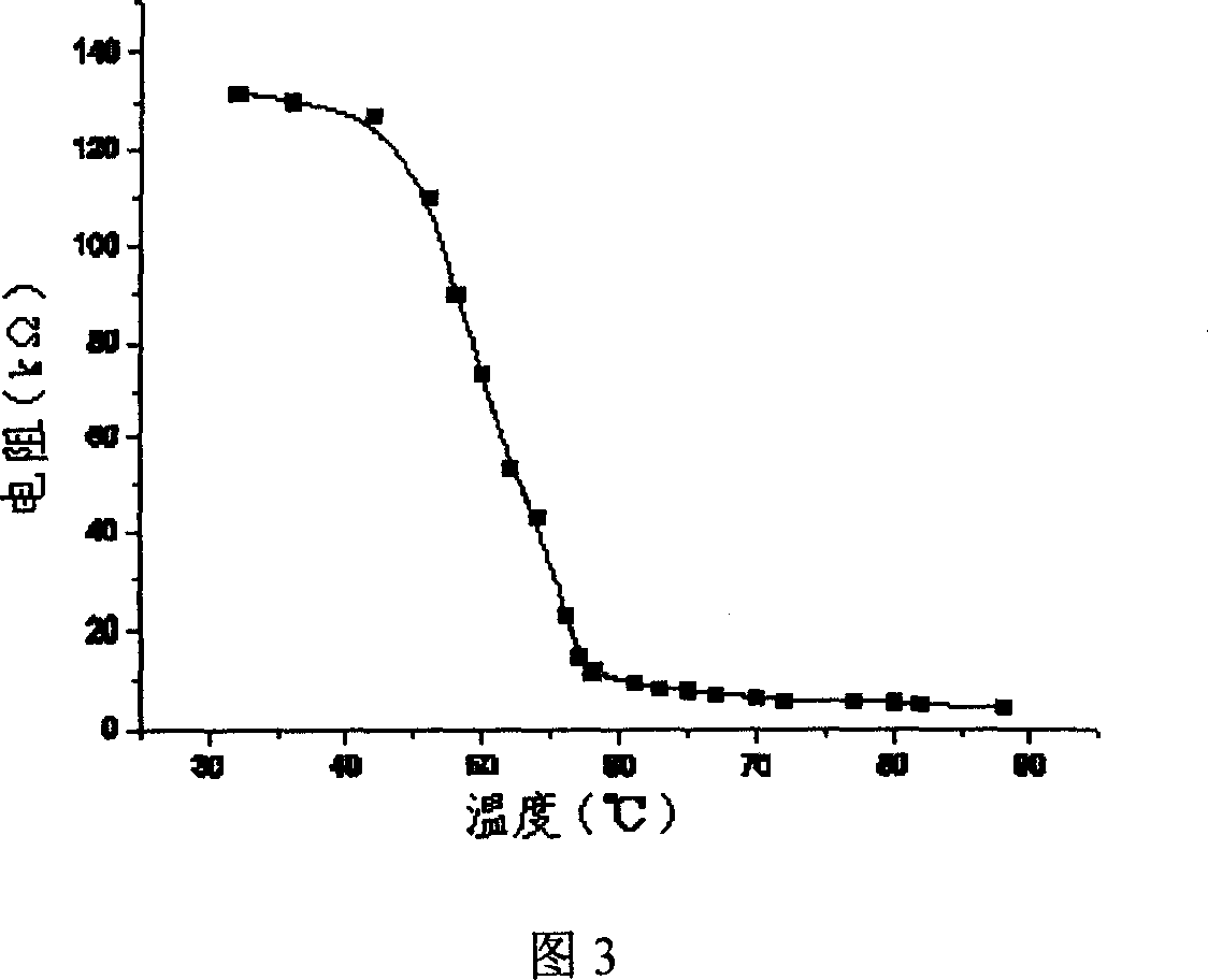
[0024] The vanadium oxide thin film obtained according to the above-mentioned embodiment is analyzed by an XPS analyzer to be a vanadium oxide mixed-phase polycrystalline thin film based on vanadium dioxide; when its resistance-temperature coefficient (T...
specific Embodiment approach 2
[0025] Steps 1 and 3 are the same, and will not be repeated here; Step 2 is: using reactive ion sputtering coating technology to prepare a vanadium oxide film, and the specific process conditions are:
[0026] Target material: pure metal vanadium; background vacuum degree: -3 Pa; Sputtering temperature: around 200°C; O 2 : Ar=1:2.0; working pressure: about 2.8Pa; O during sputtering 2 Flow: 1.8sccm; Ar flow during sputtering: about 3.9sccm; sputtering voltage: 245V;
[0027] Dynamic and precise control of the gas flow during the sputtering process until the end of the coating;
[0028] The vanadium oxide thin film obtained according to the above-mentioned embodiment is analyzed by an XPS analyzer to be a vanadium oxide mixed-phase polycrystalline thin film based on vanadium dioxide; when its resistance-temperature coefficient (TCR) is at 30° C., reach more than 5%.
specific Embodiment approach 3
[0029] Steps 1 and 3 are the same, and will not be repeated here; Step 2 is: using reactive ion sputtering coating process to prepare vanadium oxide film, and the specific process conditions are:
[0030] Target material: pure metal vanadium; background vacuum: -3 Pa; Sputtering temperature: around 200°C; O 2 : Ar=1:2.4; working pressure: about 2.8Pa; O during sputtering 2 Flow: 1.6sccm; Ar flow during sputtering: about 3.9sccm; sputtering voltage: 250V;
[0031] Dynamic and precise control of the gas flow during the sputtering process until the end of the coating;
[0032] The vanadium oxide thin film obtained according to the above-mentioned embodiment is analyzed by an XPS analyzer to be a vanadium oxide mixed-phase polycrystalline thin film based on vanadium dioxide; when its resistance-temperature coefficient (TCR) is at 30° C., Reach more than 3.2%.
PUM
 Abstract
Description
Claims
Application Information