Integrated optic grating interference micro mechanical acceleration sensor and its producing method

An acceleration sensor and grating interference technology, which is applied in the direction of measuring acceleration, optomechanical equipment, speed/acceleration/impact measurement, etc., can solve the problems of small comb gap and comb width, affecting detection accuracy, and large process limitations, etc., to achieve The effect of reducing restrictions, expanding the scope of use, and reducing the difficulty of implementation

Inactive Publication Date: 2007-06-27
TSINGHUA UNIV
View PDF1 Cites 17 Cited by
  • Summary
  • Abstract
  • Description
  • Claims
  • Application Information

AI Technical Summary

Problems solved by technology

Since the detection area cannot be too small, otherwise the incident light cannot fully irradiate the detection comb area, but this will increase the size of the entire structure; this test structure has great limitations on the process, and it does not use silicon on insulator (SOI) silicon wafers It is not easy to achieve a smaller comb gap and comb width, and the comb is easily deformed under the action of residual stress, which affects the final detection accuracy; the open-loop measurement is used, so the range is small, and the application range is greatly limited.

Method used


Image

  • Integrated optic grating interference micro mechanical acceleration sensor and its producing method
  • Integrated optic grating interference micro mechanical acceleration sensor and its producing method
  • Integrated optic grating interference micro mechanical acceleration sensor and its producing method

Examples


Embodiment 1

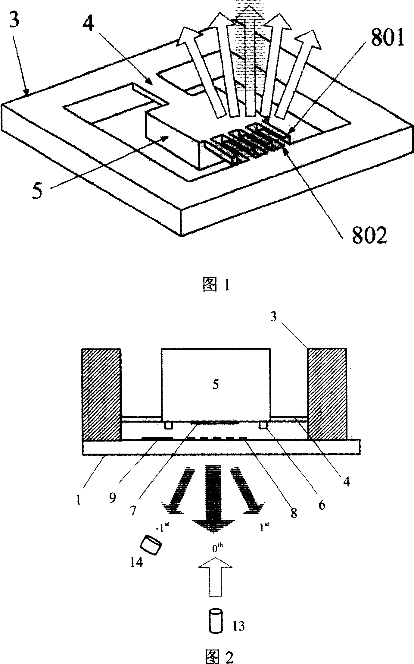
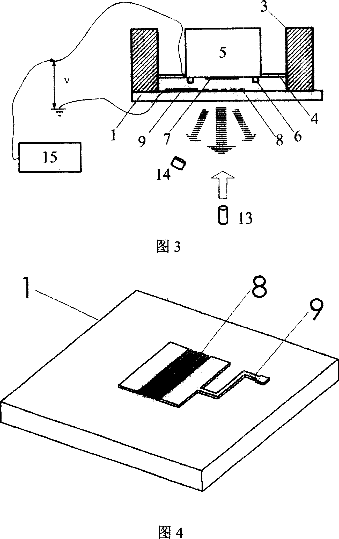
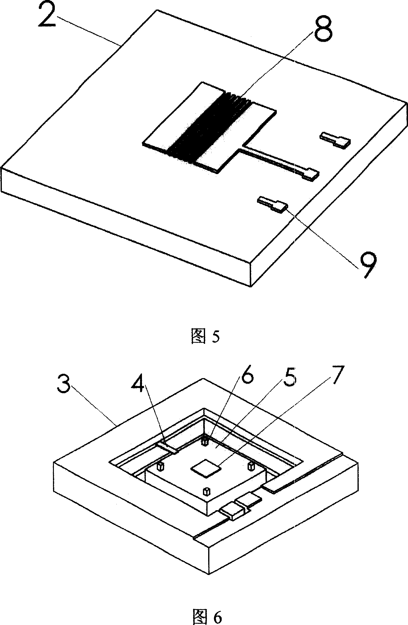
[0060] Referring to FIG. 9 , an integrated grating interference micromechanical acceleration sensor of the present invention is produced, and the sensor is composed of a first glass sheet 2 and a silicon sheet as a sensitive element. A metal grating 8 and a metal grating 9 are arranged on the first glass sheet 2 , the width of the grating bars is 5 microns, the pitch of the grating bars is 5 microns, and electrodes 9 and connection terminals 10 are also provided.

[0061] With reference to Fig. 6, described mass block 5 is set on silicon wafer 3, and this mass block 5 is provided with 4 bosses 6 with protective effect, and is plated one deck metal (or silicon) reflection surface 7 at the bottom surface of mass block 5; At least one silicon nitride beam 4 is an elastic structure used to support the mass block (silicon island) 5, the thickness of the beam can be within the range of 0.1-30 microns, the beam 4 is connected to the bottom of the mass block 5, and the beam The other ...

Embodiment 2

[0068] Referring to Fig. 10, an integrated grating interference micromachined acceleration sensor of the present invention is produced. In the present embodiment, only the structure of the support beam 4 is different from that of Embodiment 1. There are support beams around the silicon island (or both sides of the symmetry), and the support beams are about two centerlines of the silicon island (the centerline passes through the silicon island). The center point of the island, and parallel to two sets of parallel sides of the silicon island respectively) Symmetrical, the structure of the silicon wafer and the supporting beam is shown in Figure 7. In this embodiment, the number of supporting beams is at least 2, that is, there is one beam on opposite sides of the mass block; the number of supporting beams can also be 4 or an integer multiple of 4. Concrete preparation method is with embodiment 1.

Embodiment 3

[0070] Referring to Fig. 10, an integrated grating interference micromachined acceleration sensor of the present invention is fabricated. In the present embodiment, only the structure of the support beam 4 is different from that of Embodiment 1. There are support beams around the silicon island (or both sides of the symmetry), and the support beams are asymmetrical about the two center lines of the silicon island, but The center point of the silicon island is symmetrical, and the structure of the silicon wafer and the supporting beam is shown in Figure 8. In this embodiment, the number of supporting beams is at least 2, that is, there is one beam on opposite sides of the mass block; the number of supporting beams can also be 4 or an integer multiple of 4. Concrete preparation method is with embodiment 1.


PUM

PropertyMeasurementUnit
widthaaaaaaaaaa
thicknessaaaaaaaaaa
thicknessaaaaaaaaaa

Abstract

The acceleration sensor includes parts: metal grating and electrode setup on surface of the first sheet glass; mass block setup on silicon chip, N pieces of male tab setup on the mass block, and a layer of reflection plane deposited on male tabs; girder or membrane of supporting mass block, and the other end of the mass block connected to the bonding top of table-board formed from silicon chip; the face, where the metal grating and electrode are located, of the first sheet glass is opposite to the reflection plane on mass block, and the position of grating is opposite to the position of silicon island and integrated together through bonding technique; tiny gap is formed between mass block and glass so as to form sensing unit of the sensor; photoelectric detection circuit is connected to electrode of the sensing unit. By using sensibility of light intensity of grating diffracted light spot dependent on distance between grating surface and reflection plane, to implement measuring acceleration.

Description

technical field [0001] The invention belongs to the field of micro-electromechanical systems (MEMS) and sensing technologies, and in particular relates to an integrated grating interference micro-mechanical accelerometer for realizing high-resolution displacement measurement based on integrated grating interference and a manufacturing method thereof. Background technique [0002] In recent years, micromechanical sensors, especially accelerometers, made by MEMS technology have been widely used in military, automotive, aerospace, medical and other fields due to their advantages of small size, low cost, easy integration and mass production. In the fields of microgravity measurement, inclination measurement, aerospace and other fields, since the output signal of the accelerometer is relatively weak, in order to greatly improve the measurement accuracy of the sensor, on the one hand, the test circuit should be continuously improved; improve itself. At present, common detection m...

Claims


Application Information

Patent Timeline
Patent Type & Authority Applications(China)
IPC IPC(8): G01P15/093B81B7/02B81C1/00B81C3/00
Inventor 叶雄英伍康周兆英王晓浩
Owner TSINGHUA UNIV
Why Eureka
Try Eureka