
Condensate removal sootblower nozzle

a technology of condensate and blower, which is applied in the direction of flush cleaning, cleaning using liquids, lighting and heating apparatus, etc. it can solve the problems of excessive thermal and mechanical shock, slag and soot on the internal heat exchange surface of the boiler and other combustion devices, and achieve excellent performance, high dynamic cleaning effect, and reduced condensate quantity

Active Publication Date: 2018-07-10
DIAMOND POWER INT
View PDF17 Cites 1 Cited by
  • Summary
  • Abstract
  • Description
  • Claims
  • Application Information

AI Technical Summary

Benefits of technology

This patent is about a new nozzle block for a sootblower system that reduces the amount of condensate (a type of liquid) sprayed from the system. Condensate can cause damage to the boiler tubes and is normally sprayed during cleaning cycles. The new nozzle block has two separate flow paths that allow for the separation of condensate and the cleaning medium, which prevents damage to the boiler tubes. The nozzle block is made as an integral casting and has a unique design to enhance the separation of condensate. Overall, this new nozzle block improves the performance and efficiency of the sootblower system.

Problems solved by technology

During the combustion process of fossil fuels such as coal, the internal heat exchange surfaces of boilers and other combustion devices become encrusted with slag and soot.
In some conditions, when such slugs of condensate strike the boiler wall surfaces and heat transfer tubes, erosion occurs due to an excessive level of thermal and mechanical shock.
Such degradation of the heat exchange components of a boiler can cause failures and limit the operating life of the boiler which is a significant financial cost for the boiler operator.
Although such devices generally operate satisfactorily, they have a number of significant disadvantages.
For example, in some instances, such devices choke the flow of cleaning medium due to interference between the opposed cleaning medium nozzles.
Fluid flow interference caused by a disrupted cleaning medium flow at the nozzle entrance may lead to performance degradation.
Further disadvantages of known sootblower nozzle blocks for condensate ejection include the requirement of complex internal welded components which can become dislodged or deteriorate during use.
Since cleaning medium ejected along the lance tube longitudinal axis is, in most applications, not useful for providing a cleaning effect, this discharge flow constitutes an efficiency degradation of the sootblower's operating performance.
While the slot provides an effective condensate separation effect, it's cross-sectional flow area remains small, resulting in a low percentage of cleaning medium passing through the slots not available for cleaning purposes.

Method used


Image

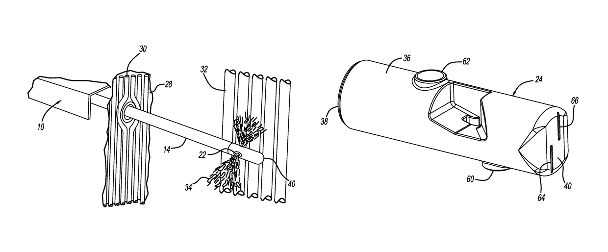
  • Condensate removal sootblower nozzle
  • Condensate removal sootblower nozzle
  • Condensate removal sootblower nozzle

Examples


first embodiment

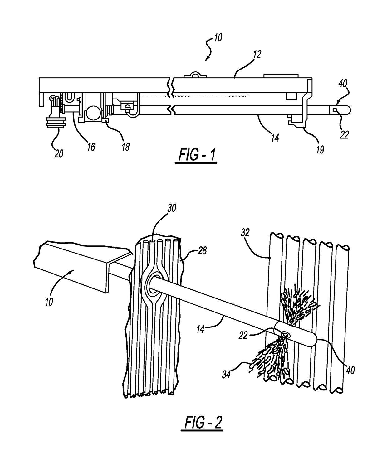
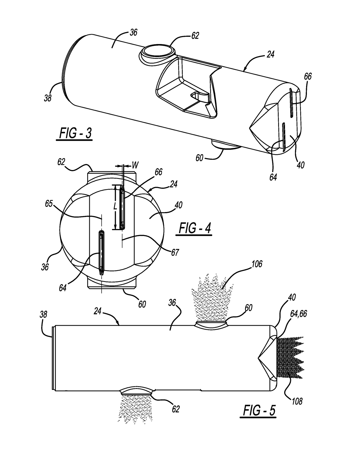
[0032]A nozzle block 24 in accordance with the present invention is illustrated in FIGS. 3 through 6 and is formed from a body or housing 36. Preferably, body 36 is formed by a casting process as will be described in further detail in the following description. Nozzle block 24 forms proximal end 38 which is affixed to a hollow lance tube 14 such as by welding. Distal end 40 is the terminal end of the lance tube assembly. Body 36 forms two internal cleaning medium passageways formed by internal wall surfaces referred to as first nozzle passageway 42 and second nozzle passageway 44. These passageways are separated by divider wall 46 extending along a diametric center plane 68 of nozzle block body 36. After cleaning medium flows into lance tube 14 and reaches divider wall 46, two separated flow streams of cleaning medium are created. For both passageways 42 and 44, the cross-sectional flow area of the flow passageway decreases from the entrance at divider wall 46 and becomes necked dow...

second embodiment

[0044]a nozzle in accordance with this invention is shown in FIGS. 14A and 14B and is generally designated by reference number 90. Nozzle block 90 does not feature the reverse direction flow paths of the previously described embodiment and does not provide a separation between two nozzle flow paths. Instead, nozzle block 90 is a cast structure in which the inside cavity of the nozzle block 90 is restricted and causes the flow of cleaning medium to undertake an approximately 90° turn at distal end 94. Nozzle block 90 uses some of the features provided by applicant's previously issued U.S. Pat. No. 6,764,030 (which is hereby incorporated by reference) in that it provides a smooth flow passageway for the cleaning medium to increase nozzle cleaning efficiency.

[0045]Nozzle block 90 incorporates one principal feature of the present invention for the ejection of condensate; namely, slot 96. Nozzle block 90 may feature a second nozzle outlet (not shown) positioned upstream of the distal end...


PUM


Abstract

A nozzle block for a sootblower of the type for cleaning internal heat transfer surfaces of large scale coal fired combustion systems. For cleaning the internal surfaces, a cleaning medium is often used in the form of steam. Due to the cyclical operations and the process of condensation, condensate slugs of water can form in the sootblower fluid flow components. If these slugs are ejected against clean surfaces, undesirable erosion can occur. Several embodiments of nozzle blocks are described each having one or more ejection ports at their distal ends configured to maximize the ejection of condensates while minimizing their cross-sectional area which would diminish nozzle fluidic efficiency. Additional features enhance the ability of the nozzle block to separate and disperse condensate from the slots.

Description

CROSS REFERENCE TO RELATED APPLICATION[0001]The present patent application claims the benefit of priority to the following applications, and is a continuation of PCT Application No. PCT / US2014 / 015209 filed Feb. 7, 2014, which claims priority to U.S. Provisional Patent Application No. 61 / 762,613, filed Feb. 8, 2013.BACKGROUND AND SUMMARY OF THE INVENTION[0002]This invention is related to a cleaning device for combustion devices and particularly to one for large scale combustion devices for the reduction of soot and / or slag encrustations forming on internal heat exchange surfaces.[0003]During the combustion process of fossil fuels such as coal, the internal heat exchange surfaces of boilers and other combustion devices become encrusted with slag and soot. In order to enhance the thermal and combustion efficiency of such devices, it is necessary to reduce the amount of encrustations on the heat exchanger surfaces. Numerous techniques for boiler cleaning are in use today. One approach i...

Claims


Application Information

Patent Timeline
Patent Type & Authority Patents(United States)
IPC IPC(8): B05B1/14B05B1/04B08B1/00B08B3/02F23J3/02F28G15/04F28G1/16F28G15/00B05B15/628F28G9/00B05B1/34F22B37/54
CPCF28G9/00B05B1/044B05B1/14B05B1/34B05B15/628F28G15/04B08B3/024F22B37/54F23J3/023F28G1/166F28G15/00B08B1/005B05B1/3402B08B1/165
Inventor HARKLEROAD, MATTHEW R.FORTNER, STEVEN R.HABIB, TONY F.BROWN, CLINTON A.
Owner DIAMOND POWER INT
Learn More