Ultra-thin dual-channel flexible circuit bridge connector

a flexible circuit and bridge connector technology, applied in the direction of fixed connections, coupling device connections, printed circuit non-printed electric components, etc., can solve the problems of insufficient flexibility, higher thickness of multi-layer flexible boards, and inability to support signal transmission between high-end graphics cards, etc., to achieve better compactness, reduce skin effect, and increase folding resistance

Inactive Publication Date: 2018-07-31
WIESON TECH CO LTD
View PDF2 Cites 5 Cited by
  • Summary
  • Abstract
  • Description
  • Claims
  • Application Information

AI Technical Summary

Benefits of technology

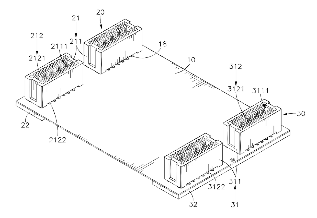
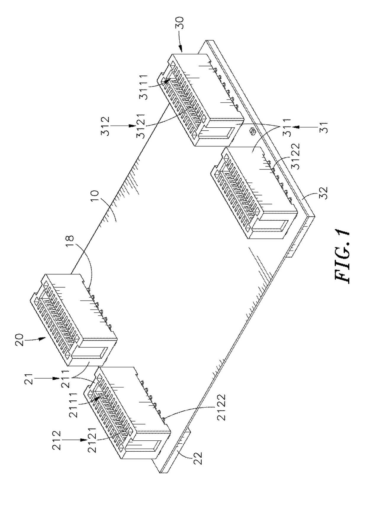
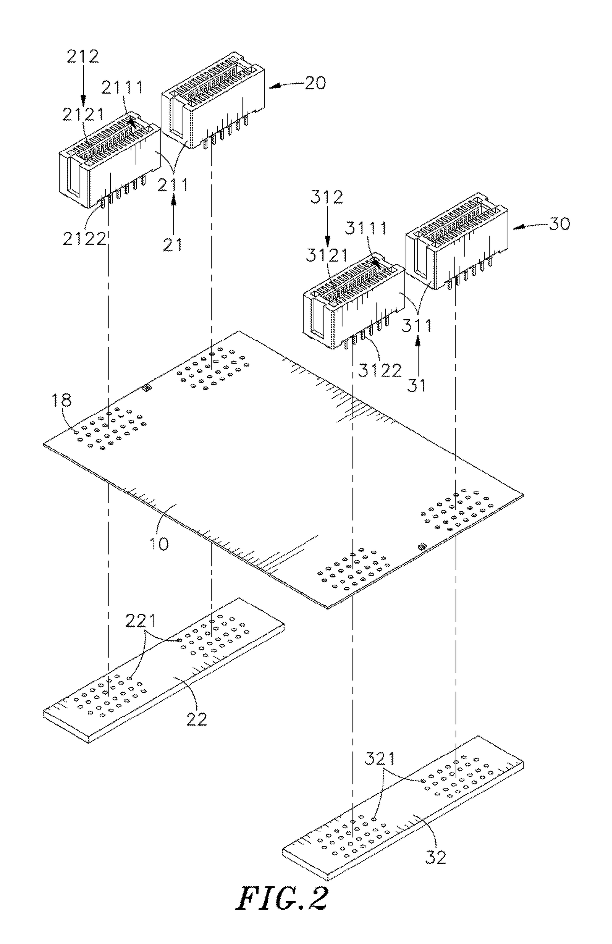
[0006]An objective of the present disclosure is to provide an ultra-thin dual-channel flexible circuit bridge connector using a dual-channel flexible circuit board. The dual-channel flexible circuit board includes, in a sequential order, a first insulating layer, a first circuit layer, a second insulating layer, a ground layer, a third insulating layer, a second circuit layer and a fourth insulating layer, and the dual-channel flexible circuit board has a total thickness in a range of 0.2 mm to 0.6 mm for better compactness, and has higher folding resistance. A first connection interface and a second connection interface are electrically connected to two sides of the first circuit layer, the ground layer and the second circuit layer, so that the first connection interface and the second connection interface can be used to link two extend interface cards spaced apart by various distances, thereby forming a bridge status. The ground layer between the first circuit layer and the second circuit layer can be served as a common reference plane for dual-channel high frequency signal transmission, so as to satisfy the requirement for working bandwidth to ensure integrity of high frequency signal, and also satisfy the requirement for characteristic impedance, and also reduce skin effect occurred in high frequency signal reflection and transmission. Furthermore, the ground layer can provide shielding and isolating effect, so disposal of the circuit layers close to the common reference plane can reduce EMI and crosstalk interference, thereby achieving stable dual-channel high frequency signal transmission and higher transmission efficiency.

Problems solved by technology

Because of limitation in flexible substrate and circuit layout used in manufacturing process of flexible board and physical limitation in structure, the dual-layer flexible board is unable to meet the requirement in high transmission rate and high efficiency.
However, with increasing of the high frequency signal transmission channel and working bandwidth of the multilayer flexible board, the multilayer flexible board may have higher thickness and insufficient flexibility, and not easily meet the requirement in characteristic impedance, and this is the reason that the conventional single-channel flexible bridge connector is mainly provided with two-layer flexible board for low data rate application, and is unable to support signal transmission between high-end graphics cards bridged with each other.
The number of layers of the circuit board indicates the number of individual circuit layers and is usually an even-number, for example, the circuit board usually has two layers, four layers or eight layers; however, the circuit board having more layers usually has higher thickness and poor flexibility, so the circuit board cannot be bent easily.
Various motherboard manufacturers or graphics card manufacturers usually have different design solutions, and it indicates that a bridging distance between two graphics cards cannot be standardized, so it is hard for one conventional dual-channel board bridge connector to bridge two graphics cards spaced apart by various distances, that is, the conventional dual-channel board bridge connector cannot meet the user's requirement in upgrade and expansion.

Method used


Image

  • Ultra-thin dual-channel flexible circuit bridge connector
  • Ultra-thin dual-channel flexible circuit bridge connector
  • Ultra-thin dual-channel flexible circuit bridge connector

Examples


Embodiment Construction

[0016]The following embodiments of the present invention are herein described in detail with reference to the accompanying drawings. These drawings show specific examples of the embodiments of the present invention. It is to be understood that these embodiments are exemplary implementations and are not to be construed as limiting the scope of the present invention in any way. Further modifications to the disclosed embodiments, as well as other embodiments, are also included within the scope of the appended claims. These embodiments are provided so that this disclosure is thorough and complete, and fully conveys the inventive concept to those skilled in the art. Regarding the drawings, the relative proportions and ratios of elements in the drawings may be exaggerated or diminished in size for the sake of clarity and convenience. Such arbitrary proportions are only illustrative and not limiting in any way. The same reference numbers are used in the drawings and description to refer to...


PUM


Abstract

The present disclosure illustrates an ultra-thin dual-channel flexible circuit bridge connector including a dual-channel flexible circuit board, a first connection interface and a second connection interface. The dual-channel flexible circuit board includes, in a sequential order, a first insulating layer, a first circuit layer, a second insulating layer, a ground layer, a third insulating layer, a second circuit layer and a fourth insulating layer. The first connection interface and the second connection interface can be used to link two extend interface cards spaced apart by various distances, thereby forming a bridge status. The ground layer between the first circuit layer and the second circuit layer can be served as a common reference plane for dual-channel high frequency signal transmission and provide shielding and isolating effect, so as to satisfy the requirement for working bandwidth to satisfy the requirement for characteristic impedance, reduce skin effect, reduce EMI and crosstalk interference.

Description

BACKGROUND OF THE INVENTION1. Field of the Invention[0001]The present disclosure relates to an ultra-thin dual-channel flexible circuit bridge connector, more particularly to an ultra-thin dual-channel flexible circuit bridge connector using a dual-channel flexible circuit board to link two extend interface cards spaced apart by various distances, so as to form a bridge status. Furthermore, the ultra-thin dual-channel flexible circuit bridge connector of the present disclosure can meet the requirement in characteristic impedance during high frequency signal transmission and reduce electromagnetic wave interference (EMI), thereby achieving stable dual-channel high frequency signal transmission and higher transmission efficiency.2. Description of the Related Art[0002]With rapid development in the electronic technology, a computer or a server has higher and higher computing speed and efficiency. The computer or the server includes a motherboard, and a central processor and a memory dis...

Claims


Application Information

Patent Timeline
Patent Type & Authority Patents(United States)
IPC IPC(8): H05K1/00H05K1/18H05K3/36H01R12/59H05K1/14H05K3/34H01R12/77
CPCH05K1/189H05K3/363H01R12/59H05K1/148H05K3/3457H01R12/778H05K2201/2009H01R12/61H01R13/6461H05K1/117H05K1/147H05K3/3447H05K3/366H05K3/368H05K2201/09327H05K2201/10189
Inventor HU, QIANG-LONGLIU, WEN-SHENG
Owner WIESON TECH CO LTD
Why Eureka
Try Eureka