Ultrafast MRI system and method

a magnetic resonance imaging and ultra-fast technology, applied in the field of imaging, can solve the problems of inhomogeneity of magnetic field, inefficiency of spatial sensitivity encoding, and inability to detect changes in susceptibility,

Active Publication Date: 2018-10-23
HUTCHINSON MICHAEL
View PDF8 Cites 1 Cited by
  • Summary
  • Abstract
  • Description
  • Claims
  • Application Information

AI Technical Summary

Benefits of technology

[0013]One example of the new approach comprises a gantry with a magnet configured to generate a main magnetic field B0 in an imaging volume, a gradient field generator configured to generate a steady gradient field g in the imaging volume, a radio-frequency (RF) pulse generator configured to apply an excitation RF pulse to the imaging volume, and a multitude of small MR signal receiving coils arranged in a three-dimensional (3D) array surrounding the imaging volume and extending along the B0 field. Each of the receiver coils is configured to simultaneously receive RF energy from the entire imaging volume during MR signal acquisition and output respective MR signals. An MR signal acquisition facility acquires the MR signals and a computer-implemented processor applies image reconstruction algorithms to the MR signals and thereby generates a 3D image of an object in the imaging volume, displayed as such or as two-dimensional (2D) images derived therefrom. The MR signal from each of the coils comprises a time sequence of overall peaks and valleys that can extend over a period of the order of seconds and even minutes in response to the RF pulse, without requiring additional MR signal-encoding RE pulses or MR signal-encoding gradient reversals for spatial encoding or rephasing.

Problems solved by technology

An advantage of using gradient reversals is speed; a disadvantage is sensitivity to susceptibility changes and magnetic field inhomogeneities.
Sources of electrical noise include preamplifiers, coupling between adjacent coils, and body thermal noise.
In addition, there is noise from the eddy currents in the body surface due not only to the gradient reversals but also to re-radiation of signal by the coil, which is both a receiver and a dipole radiator.
When multiple coils are used to encode, however, there can be an additional problem due to the inefficiency of spatial sensitivity encoding, compared with gradient encoding, when the coils are large.
It has generally been accepted that for practical purposes this single limitation means that for hybrid techniques acceleration factors need to be at most about 4, so that the rate of acquisition of SNR is about double that of non-parallel techniques.
However, this was not for volume encoding but only for a single slice.
This can generate a large amount of noise, first RF and other electrical noise, and second audible noise.
This means that image signal-to-noise ratio is lowered, and that the machine can be extremely loud (up to 120 dB).

Method used


Image

  • Ultrafast MRI system and method
  • Ultrafast MRI system and method
  • Ultrafast MRI system and method

Examples


Embodiment Construction

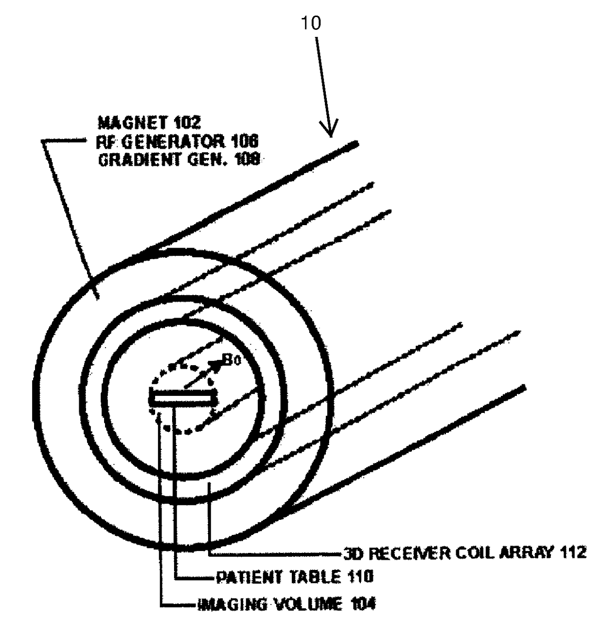
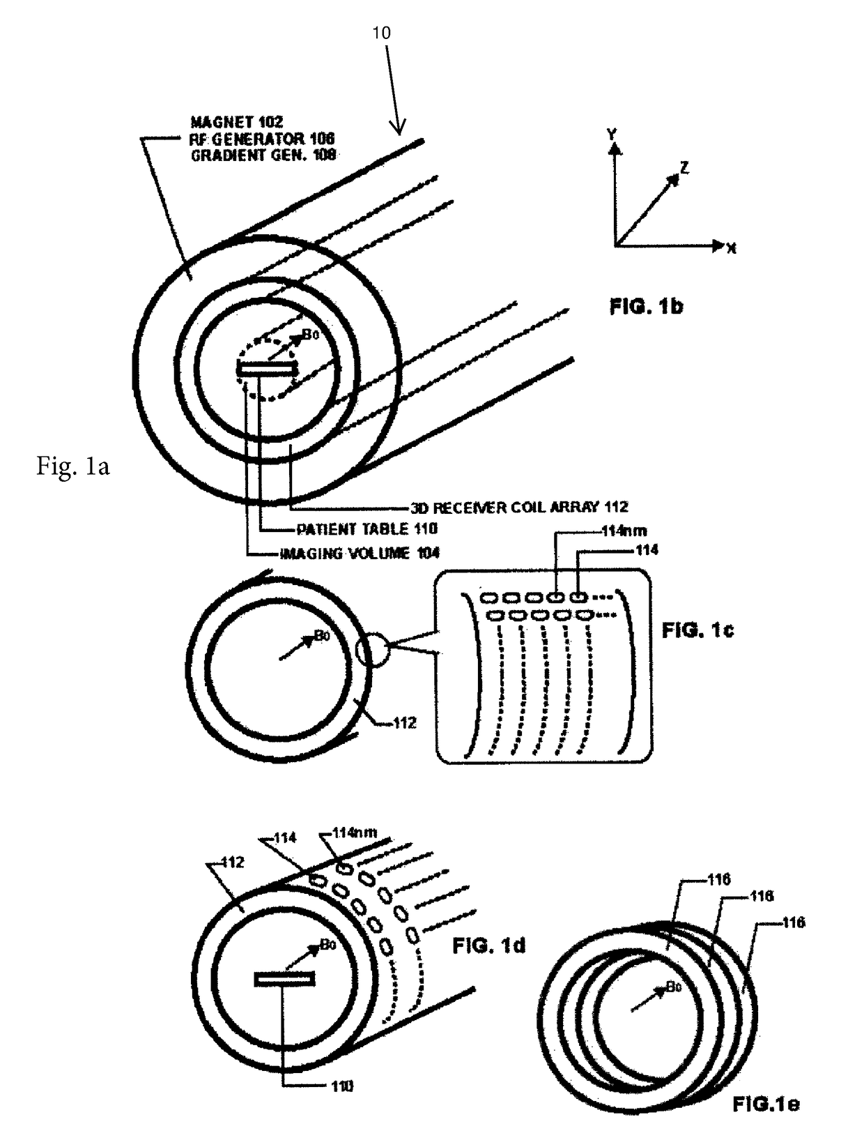
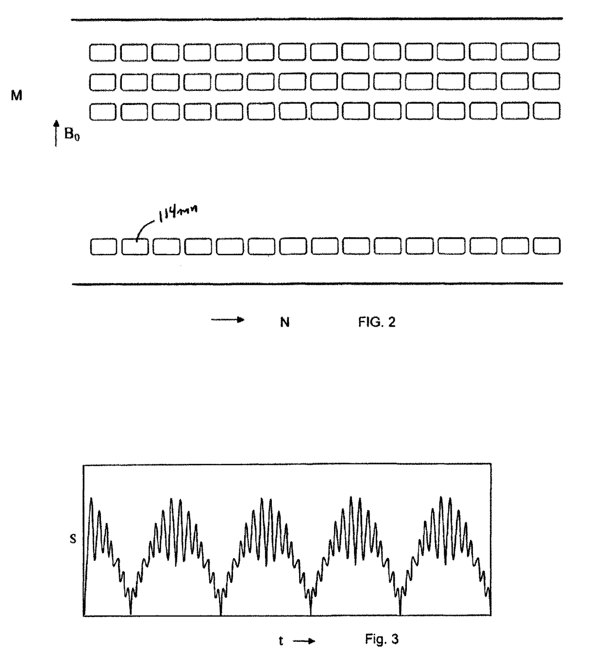
[0021]An example of a preferred embodiment can operate by using some of the basic components of a conventional MRI system, such as a magnet generating a main magnetic field B0 in an imaging volume, a source of RF excitation pulses, a source of an a magnetic gradient, a computer configured to process MR signals and to control the overall operation of the system, and a workstation to format and process MR images and allow operator control. The new approach described in this patent specification adds other components, and programs the computer in the system to carry out different operations. The new components include a drastically different 3D array of very small receiver coils surrounding the imaging volume where the output of each of the small coils is an MRI signal comprising contributions from the entire imaging volume. The new approach further includes modifications in the control over, and if desired the structure of, the RF pulse and gradient generators, and providing a differe...


PUM


Abstract

Magnetic Resonance Imaging (MRI), which is given the acronym ULTRA (Unlimited Trains of Radio Acquisitions), can eliminate magnetic gradient reversals and allow simultaneous MR signal acquisition from the entire object volume in each of a multitude of very small receiver coils arranged in a 3D array around the imaging volume. This permits a rate of MR signal acquisition that is greatly increased (e.g. 256 times) compared with existing techniques, with a full 3D image constructed in as little as 1 millisecond. Furthermore, noise—both audible and electrical—is substantially reduced. The advantages over conventional MRI include:1. Clinical imaging can be completed in seconds, with good signal-to-noise ratio;2. Signal-to-noise ratio is further increased by eliminating RF noise due to gradient switching;3. Real-time functional MRI is possible, on millisecond timescales;4. With single breath holds, high quality imaging of thorax and abdomen is possible.5. ULTRA greatly reduces audible noise and vibration.

Description

FIELD[0001]This patent specification is in the field of imaging, such as medical imaging, and more specifically relates to rapid three-dimensional (3D) magnetic resonance imaging (MRI).BACKGROUND[0002]Several references are identified by numerals in parenthesis in this patent specification, and are hereby incorporated by reference. The full citations are listed at the end of the specification. Reference [18] is a paper by the inventor and a person working under his direction regarding the subject matter of the paper.[0003]Real-time MR imaging could exert a profound influence on neuroscience in the future by enabling the direct visualization of neuronal interactions. At this time, however, the known practical embodiments of MRI require at least some degree of gradient encoding, and this in turn sets a lower limit of about 100 ms for volume acquisition.[0004]In the original formulation of MRI by Lauterbur [1], spatial encoding is achieved by applying successive magnetic field gradient...

Claims


Application Information

Patent Timeline
Patent Type & Authority Patents(United States)
IPC IPC(8): G01R33/561G01R33/3415G01R33/32G01R33/387G01R33/50G01R33/565A61B5/055G01R33/483
CPCG01R33/5611G01R33/3415G01R33/561G01R33/483A61B5/055
Inventor HUTCHINSON, MICHAEL
Owner HUTCHINSON MICHAEL
Why Eureka
Try Eureka