Preparing tool surfaces for composites
- Summary
- Abstract
- Description
- Claims
- Application Information
AI Technical Summary
Benefits of technology
Problems solved by technology
Method used
Image
Examples
example 1
[0085]The objective of this experiment was to eliminate composite pitting by coating the Al tool with a porous fluorocarbon film. The porous fluorocarbon film was deposited on the aluminum by atmospheric pressure, plasma-enhanced chemical vapor deposition. It was hoped that this film would provide for suitable release of the composite from the tool, and for easy escape of gas bubbles during curing.
[0086]The average water contact angle (WCA) measured on the surface of an Al tool after it has been properly cleaned and treated with Frekote was 106±1°. A Kruss DSA 15B digital goniometer with DSA 3 software package was used to capture the WCA of a 1 μL droplet of deionized water on the surface. Helium and octofluorocyclobutane (C4F8) was fed to an atmospheric pressure plasma (Surfx Technologies Atomflo 400 with a 250-D showerhead source). At the same time, ethylene (C2H4) was fed through a gas distributor into the afterglow immediately below the plasma outlet. The reactive gas flow rates...
example 2
[0090]The anodized aluminum tool was treated with Frekote mold release, and then used to fabricate an OoA composite using the procedures described above. A picture of the resulting composite panel is shown in FIG. 16. No surface porosity is detected in the measurement area shown by the white circle. This unexpected result proves the ability of a tool with a microstructure to produce out-of-autoclave composites with a smooth surface finish. It was further found that the microstructure created by anodization of the aluminum could only be used once, and could not be used repeatedly to generate a smooth OoA composite. This led us to develop further inventive methods and microstructures to solve the pitting problem.
example 3
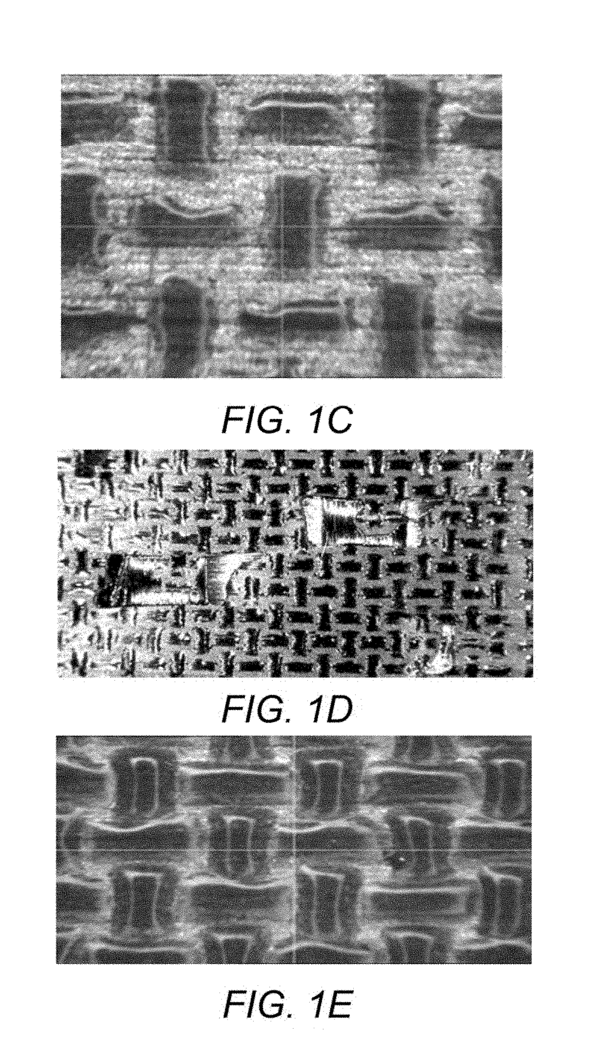
[0091]In this example, an ordered microstructure, similar to that found on the Taconic woven release ply was deposited directly onto the aluminum tool. The patterned film was deposited onto the metal surface using a Dimatix Materials Printer DMP-3000 with a positional accuracy and repeatability of ±5 and ±1 μm, respectively. The material deposited onto the tool was an acrylic ink that was quickly cured using ultraviolet light. A flat 260×260 mm2 Al tool was printed with a 155×155 mm2 grid that comprised overlapping horizontal and vertical lines. The lateral height profile of the film deposited by the inkjet printing technique is shown in FIG. 17. An optical micrograph of the film at 30× magnification is presented in FIG. 18. The printed acrylic pattern exhibited a height of 17 microns with a lateral spacing of approximately 350 microns. Note also the shape / distribution of the material within each “hill” of the grid is much sharper compared to the woven release ply, i.e., FIG. 6. Thi...
PUM
| Property | Measurement | Unit |
|---|---|---|
| Length | aaaaa | aaaaa |
| Height | aaaaa | aaaaa |
| Height | aaaaa | aaaaa |
Abstract
Description
Claims
Application Information
 - R&D
- Intellectual Property
- Life Sciences
- Materials
- Tech Scout
- Unparalleled Data Quality
- Higher Quality Content
- 60% Fewer Hallucinations
Browse by: Latest US Patents, China's latest patents, Technical Efficacy Thesaurus, Application Domain, Technology Topic, Popular Technical Reports.
© 2025 PatSnap. All rights reserved.Legal|Privacy policy|Modern Slavery Act Transparency Statement|Sitemap|About US| Contact US: help@patsnap.com


