
Selective plant detection and treatment using green luminance photometric machine vision scan with real time chromaticity operations and image parameter floors for low processing load

a technology of green luminance and machine vision, applied in image enhancement, camera filters, instruments, etc., can solve the problems of reducing the use of pesticides for weed and plant control, adversely affecting the quality of ground water, and affecting the human nervous system, etc., to achieve low processing overhead, simple steps, and complex calibration

Active Publication Date: 2019-04-23
GLOBAL NEIGHBOR
View PDF26 Cites 2 Cited by
  • Summary
  • Abstract
  • Description
  • Claims
  • Application Information

AI Technical Summary

Benefits of technology

This approach allows for efficient, real-time detection and treatment of target plants with reduced computational load, minimizing pesticide use and environmental impact while maintaining high accuracy, thus addressing the inefficiencies and environmental concerns of existing systems.

Problems solved by technology

Reducing the use of pesticides for weed and plant control has become an issue of national importance.
Ground water is vitally important and the use of herbicides to prevent weeds from growing in homeowner and commercial lawns adversely impacts the quality of ground water.
Most herbicides are persistent, soluble in water, and ingestion at high toxicity levels can be carcinogenic, affecting the human nervous system and causing endocrine disruption.
Large land areas under treatment consume large volumes of liquid or other treatments, a huge expense and a labor intensive task for distribution.
Although some plants can be characterized via spectral analysis of light reflected off from leaves and stems, etc., this type of detection requires special arrangements, calibrations, processing demands and software, and is prone to error and non-operation due to local conditions, plant variations, moisture and soil on leaves, and the effects of recent sun exposure history, which can change the tone or color of leaves and plant parts, which adapt to irradiation, often for protection against internal scalding.
In the use of field images to detect target plants (as defined below), the use of color is complex and critical.
Much of the prior art utilizes radiometric, physical methods in image analysis, and this introduces difficulties because detection of target plants is subtle and happens to be something that humans perform well and easily when compared to physical methods, such as spectral analysis.
In the prior art, detecting target plants, as opposed to merely detecting a plant—is considered difficult without using very high processing power which analyzes on a sophisticated level, such as by comparing plant images to images stored in a database.
This is cumbersome, involves expensive components to form a spectrometer, and increases processing requirements.
The reliance on spectrum data makes the method vulnerable to local plant reflectance characteristics, local conditions like rain drops, invites high error rates, and requires extensive calibrations.
The Weed Seeker® automatic spot spray system of Trimble, Inc., (Sunnyvale, Calif., USA) seeks green plants for reductive or eradication spraying, and uses expensive sophisticated processing.
US Patent Publication 20150309496 to KAH III of K-RAIN Manufacturing Corporation, teaches use of a database of reference data for comparison, which introduces a high computational overhead, as image comparison algorithms must perform complex calculations, and pass through logic trees after what is often pixel-by-pixel comparisons.
This also introduces large processing overhead and the need for uninterrupted communication with a database.

Method used


Image

  • Selective plant detection and treatment using green luminance photometric machine vision scan with real time chromaticity operations and image parameter floors for low processing load
  • Selective plant detection and treatment using green luminance photometric machine vision scan with real time chromaticity operations and image parameter floors for low processing load
  • Selective plant detection and treatment using green luminance photometric machine vision scan with real time chromaticity operations and image parameter floors for low processing load

Examples


Embodiment Construction

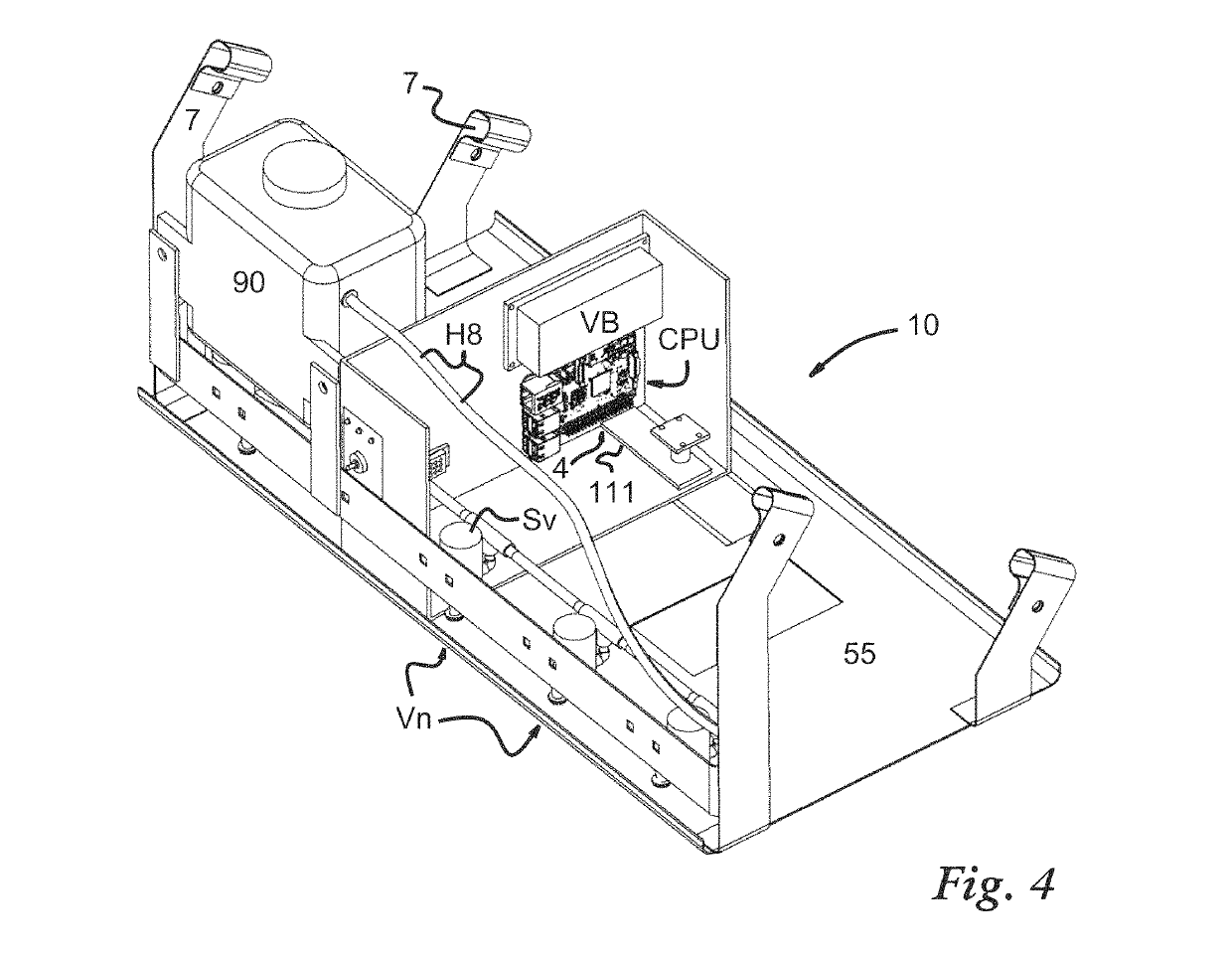
[0088]Now referring to FIGS. 4 and 5, oblique, partial surface views of an illustrative target plant detection and treatment system according to the invention are shown. Constituent components affixed to chassis 55 of a target plant detection and treatment system 10 as shown include a known single board computer CPU affixed there and in communication with field image camera with fisheye lens 4, which is not explicitly shown but can use known low cost CMOS active pixel sensors, and is trained downward upon a field as shown on the page, ready to gather a field image (shown, FIELD IMAGE). The single board computer CPU alone does all image capture processing and analysis, using machine instructions programmed as alluded to below. A light source strip 111 is also trained downward and can include commonly available known LED (Light Emitting Diode) lighting that consumes power on the order of single watts. Imaging can occur at various light intensity levels, but the use of supplemental ill...


PUM


Abstract

A field image is formed using a tristimulus color model and used to detect target plants or entities on a field. Through the use of a luminance parameter floor, hue and saturation selection steps, feature recognition, a sizing floor and an aspect ratio ceiling, a very fast way is devised to recognize a target plant without need for consulting plant attribute databases, or to analyze spectral or other specialized data for comparison with known attributes. This allows a low calculational processing load and use of simple hardware such as a single board computer to handle machine vision in real time. Treatment steps can include a spray event, a light treatment, and a thermal / mechanical trauma.

Description

TECHNICAL FIELD[0001]This invention relates to detection and elimination of broadleaf weeds and target plants using methods that insure processing with a low computational load and no need to consult certain databases, but it can apply generally to detection and correction of defects in manufactured products and the like. The teachings herein can be used for many purposes, including plant and weed control using selective targeted spray treatment, illumination trauma and thermal / mechanical trauma.[0002]The invention can be used to delivery thermal / mechanical trauma, such as that stab unit of an invasive hot stab plant eradicator as disclosed in U.S. Pat. Nos. 7,954,276 and 8,141,292, and 8,365,464 to Jackson, all of which are hereby incorporated herein by reference in their entirety.[0003]The use of the invention in conjunction with the delivery of selective illumination trauma relates to a relatively low energy rapid unnatural illumination protocol of duration less than one minute t...

Claims


Application Information

Patent Timeline
Patent Type & Authority Patents(United States)
IPC IPC(8): G06T7/00H04N9/04G06T7/90H04N9/00H04N5/232A01M21/04A01M21/02A01M7/00G03B11/00G06K9/46G06T11/60G06T7/11G06K9/62G06V10/143
CPCG06T7/0004A01M7/0089A01M21/02A01M21/04A01M21/043G03B11/00G06K9/4661G06K9/6267G06T7/11G06T7/90G06T11/60H04N5/23229H04N5/23293H04N9/00H04N9/04G06T2207/20224G06T2207/30188G06T7/0012G06V20/10G06V10/143H04N23/84H04N9/64G06F18/24H04N23/10H04N23/63H04N23/80
Inventor JACKSON, JONATHAN ANOVOTNEY, NORMANCARTER, CHRISTOPHERERDMAN, AUSTINJACKSON, PATRICK A
Owner GLOBAL NEIGHBOR
Learn More